Nissan Juke Service and Repair Manual : Operation
Switch Name and Function
OPERATION AND DISPLAY
A/C Display (Display in Multi Display Unit)
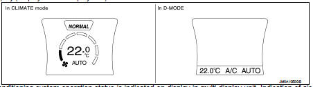
• Air conditioning system operation status is indicated on display in multi display unit. Indication of air conditioning system varies according to display mode of multi display unit. For changing procedure of display mode, refer to AV-99, "NISSAN DYNAMIC CONTROL SYSTEM : System Description".
- In CLIMATE mode: Operation status of air conditioning system (setting temperature, air flow, and “AUTO”*1) is indicated on display when air conditioning system is turned ON.
- In D-MODE: Operation status of air conditioning system (setting temperature, A/C switch, and “AUTO”*2) is indicated on lower portion of display when air conditioning system is turned ON.
NOTE
:
*1: AUTO is indicated when both air flow and air outlet are in automatic
control.
*2: Air Flow is indicated when air flow or air outlet is in manual control.
A/C Controller (Multi Display Unit) Operation procedure of air conditioning system varies depending on display mode of multi display unit. For changing procedure of display mode, refer to AV-99, "NISSAN DYNAMIC CONTROL SYSTEM : System Description".
• In CLIMATE mode: All operations of air conditioning system are possible.
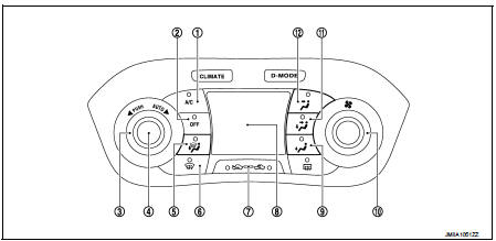
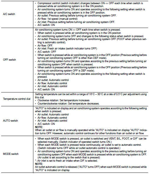
1. A/C switch
2. OFF switch
3. Temperature control dial
4. AUTO switch
5. MODE switch (D/F)
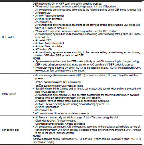
6. DEF switch
7. Intake switch
8. Display
9. MODE switch (FOOT)
10. Fan control dial
11. MODE switch (B/L)
12. MODE switch (VENT)
• In D-MODE: The following switches and dial cannot be operated.
- A/C switch
- OFF switch
- MODE switch
- Fan control dial
 System
System Diagram
System Description
DESCRIPTION
• Automatic air conditioning system is controlled by each function of A/C
auto amp., BCM, ECM and IPDM E/
R.
• Each operation of air conditioning ...
 Diagnosis system (A/C auto AMP.)
Description
Air conditioning system performs self-diagnosis, operation check, function
diagnosis, and various settings
using diagnosis function of each control unit.
CONSULT-III Function
CONSU ...
Other materials:
Fuel injector
Component Function Check
1.INSPECTION START
Turn ignition switch to START.
Is any cylinder ignited?
YES >> GO TO 2.
NO >> Proceed to EC-400, "Diagnosis Procedure".
2.CHECK FUEL INJECTOR FUNCTION
With CONSULT-III
1. Start engine.
2. Perform “POWER BALANCE” in “ACT ...
U1001 Can comm circuit
Description
CAN (Controller Area Network) is a serial communication line for real time
application. It is an on-vehicle multiplex
communication line with high data communication speed and excellent error
detection ability. Many electronic
control units are equipped onto a vehicle, and each c ...
Push starting
Do not attempt to start the engine by pushing.
CAUTION
• Continuously Variable Transmission (CVT) models cannot be pushstarted or
tow-started. Attempting to do so may cause transmission damage.
• Three-way catalyst equipped models should not be started by pushing since the
three way catalyst ...
