Nissan Juke Service and Repair Manual : Oil pan (lower)
Exploded View
With Oil Cooler
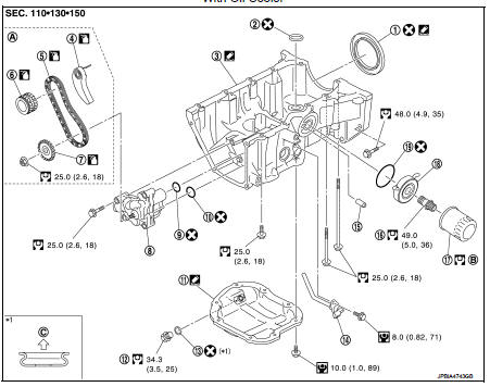
1. Rear oil seal
2. O-ring
3. Oil pan (upper)
4. Oil pump chain tensioner (for oil
pump drive chain)
5. Oil pump drive chain
6. Crankshaft sprocket
7. Oil pump sprocket
8. Oil pump
9. O-ring
10. O-ring
11. Oil pan (lower)
12. Oil pan drain plug
13. Drain plug washer
14. Oil level sensor
15. Relief valve
16. Connector bolt
17. Oil filter
18. Oil cooler
19. O-ring
A. Refer to EM-182
B. Refer to LU-28
C. Oil pan (lower) side
 : Always replace after every
disassembly.
 : N·m (kg-m, in-lb)
 : N·m (kg-m, ft-lb)
 : Sealing point
 : Should be lubricated with oil
With Out Oil Cooler
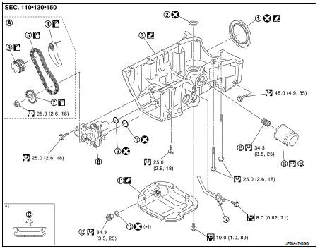
1. Rear oil seal
2. O-ring
3. Oil pan (upper)
4. Oil pump chain tensioner (for oil
pump drive chain)
5. Oil pump drive chain
6. Crankshaft sprocket
7. Oil pump sprocket
8. Oil pump
9. O-ring
10. O-ring
11. Oil pan (lower)
12. Oil pan drain plug
13. Drain plug washer
14. Oil level sensor
15. Oil filter stud bolt
16. Oil filter
A. Refer to EM-182
B. Refer to LU-28
C. Oil pan (lower) side
: Always replace after every
disassembly.
: N·m (kg-m, in-lb)
: N·m (kg-m, ft-lb)
: Sealing point
: Should be lubricated with oil
Removal and Installation
REMOVAL
1. Drain engine oil. Refer to CO-11, "Draining".
2. Remove oil pan (lower) with the following procedure:
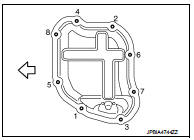
a. Loosen mounting bolts in reverse order as shown in the figure.
 : Engine front
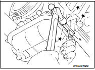
![b. Insert seal cutter [SST: KV10111100] (A) between oil pan (upper)](images/books/335/5/index.3.jpg)
b. Insert seal cutter [SST: KV10111100] (A) between oil pan (upper) and oil pan (lower).
CAUTION:
• Be careful not to damage the mating surface.
• Never insert a screwdriver. This damages the mating surfaces.
c. Slide the seal cutter [SST: KV10111100] by tapping on the side of tool with a hammer.
d. Remove oil pan (lower).
INSTALLATION
1. Install oil pan (lower) as follows: a. Use a scraper (A) to remove old liquid gasket from mating surfaces.
• Also remove old liquid gasket from mating surface of oil pan (upper).
• Remove old liquid gasket from the bolt holes and threads.
CAUTION:
Never scratch or damage the mating surface when cleaning
off old liquid gasket.
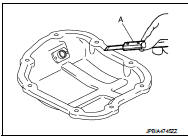
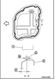
b. Apply a continuous bead of liquid gasket (B) with a tube presser (commercial service tool) as shown in the figure.
a : 7.5 - 9.5 mm (0.295 - 0.374 in)
c : φ4.0 - 5.0 mm (0.157 - 0.197 in)
1 : Oil pan (lower)
 : Engine outside
Use Genuine Liquid Gasket or equivalent.
CAUTION:
Attaching should be done within 5 minutes after liquid gasket
application.
c. Tighten bolts in numerical order as shown in the figure.
: Engine front
2. Install oil pan drain plug.
• Refer to the figure of components of former page for installation direction of drain plug washer. Refer to EM-169, "Exploded View".
3. Install in the reverse order of removal after this step.
NOTE
:
Wait at last 30 minutes after oil pan (lower) is installed before pouring engine
oil.
Inspection
INSPECTION AFTER REMOVAL
Clean oil strainer if any object attached.
INSPECTION AFTER INSTALLATION
1. Check the engine oil level and adjust engine oil. Refer to LU-25, "Inspection".
2. Start engine, and check there is no leakage of engine oil.
3. Stop engine and wait for 10 minutes.
4. Check the engine oil level again. Refer to LU-25, "Inspection".
 Exhaust manifold
Exploded View
1. Exhaust manifold cover
2. Harness bracket
3. Air fuel ratio sensor 1
4. Exhaust manifold stay
5. Heat insulator
6. Exhaust manifold
7. Exhaust manifold cover
8. Gasket ...
 Fuel injector and fuel tube
Exploded View
1. Stud bolt
2. O-ring (green)
3. Fuel injector (front)
4. Clip
5. Fuel injector (rear)
6. O-ring (black)
7. Fuel tube protector
8. Fuel tube
9. Fuel feed hose
10. Qui ...
Other materials:
Wiring diagram
AUDIO WITH NAVIGATION
Wiring Diagram
For connector terminal arrangements, harness layouts, and alphabets in a
(option abbreviation; if not
described in wiring diagram), refer to GI-12, "Connector Information/Explanation
of Option Abbreviation".
...
Safety note
WARNING
• Do not disassemble or modify this system. If you do, it may result in accidents,
fire, or electric shock.
• Do not use this system if you notice any abnormality, such as a frozen screen
or lack of sound. Continued use of the system may result in accident, fire or electric
shock.
• ...
Ignition position warning function does not operate
Diagnosis Procedure
1.CHECK DTC WITH BCM
Check that DTC is not detected with BCM.
Is the inspection result normal?
YES >> GO TO 2.
NO >> Refer to BCS-67, "DTC Index".
2.CHECK POWER DOOR LOCK OPERATION
Check power door lock operation.
Does door lock/unlock with d ...
