Nissan Juke Service and Repair Manual : Oil pan
Exploded View
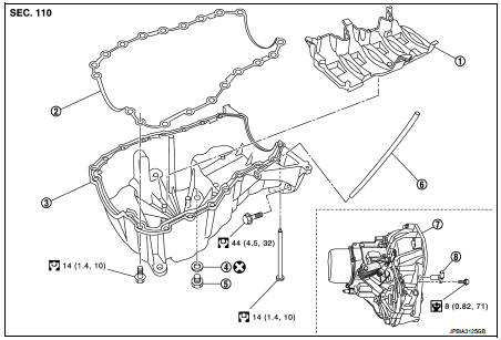
1. Baffle plate
2. Gasket
3. Oil pan
4. O-ring
5. Drain plug
6. Oil level gauge guide
7. Transaxle
8. Crankshaft position sensor (POS)
 : N·m (kg-m, ft-lb)
 : N·m (kg-m, in-lb)
 : Always replace after every
disassembly.
Removal and Installation
REMOVAL
CAUTION:
Never drain engine oil when the engine is hot to avoid the danger of being
scalded.
1. Remove engine under cover.
2. Remove RH front wheel. Refer to WT-7, "Exploded View".
3. Remove fender protector RH. Refer to EXT-22, "Exploded View".
4. Remove engine mounting bracket. Refer to EM-326, "Exploded View".
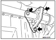
5. Remove center bearing bracket as shown.
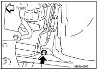
6. Remove A/C compressor bracket mounting bolt as shown.
7. Remove oil level gauge guide.
8. Drain engine oil. Refer to LU-34, "Draining".
CAUTION:
Perform when engine is cold.
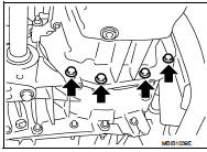
9. Remove oil pan and transaxle joint bolts.
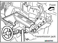
10. Support the engine bottom of the oil pan with a transmission jack etc.
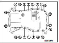
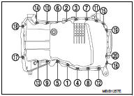
11. Remove oil pan bolt reverse order as shown.
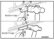
• Insert seal cutter (special service tool) between upper oil pan and cylinder block. Slide tool by tapping on the side of the tool with a hammer.
CAUTION:
Exercise care not to damage mating surface.
12. Remove oil pan and baffle plate.
INSTALLATION
• Install in the reverse order of removal paying attention to the following.
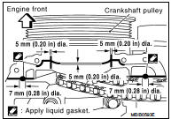
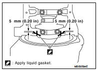
1. Apply liquid gasket as shown.
• Use Genuine Liquid Gasket or equivalent.
2. Install baffle plate.
3. Install oil pan.
• Tighten the mounting bolts of oil pan on the clutch housing without locking.
• Tighten the bolts in the numerical order shown in the figure.
 : 14 N·m (1.4 kg-m, 10 ft-lb)
• Tighten the mounting bolts of oil pan on the clutch housing.
 : 44 N·m (4.5 kg-m, 10 ft-lb)
4. At least 30 minutes after oil pan is installed, pour engine oil.
Inspection
INSPECTION AFTER REMOVAL
Clean oil pump assembly if any object attached.
INSPECTION AFTER INSTALLATION
• Inspection the engine oil level. Refer to LU-33, "Inspection".
• Start the engine, and make sure there is no leak of engine oil. Refer to LU-33, "Inspection".
 Exhaust manifold
Exploded View
1. Exhaust gas temperature sensor 1
2. Gasket
3. Exhaust manifold
4. Exhaust gas pressure sensor 1
A. To cylinder head
: N·m (kg-m, ft-lb)
: Always replace after every
disas ...
 Glow plug
Exploded View
1. Glow plug
Engine front
: N·m (kg-m, ft-lb)
Removal and Installation
REMOVAL
CAUTION:
Remove glow plug only if necessary. If carbon adheres, it may be stuck and
broken.
1. ...
Other materials:
Key warning lamp
Component Function Check
1.CHECK FUNCTION
1. Select “INTELLIGENT KEY” of “BCM” using CONSULT-III.
2. Select “INDICATOR” in “ACTIVE TEST” mode.
3. Check that the function operates normally according to the following
conditions.
Is the inspection result normal?
YES >> Key warning lamp ...
Emission control not satisfactory
Description
CHART 22: EMISSION CONTROL NOT SATISFACTORY
Diagnosis Procedure
1.CHECK ECM POWER SUPPLY AND GROUND CIRCUIT
Check ECM power supply and ground circuit. Refer to EC-885, "Diagnosis
Procedure".
Is the inspection result normal?
YES >> GO TO 2.
NO >> Repair ...
Diagnosis system (BCM)
Common item
COMMON ITEM : CONSULT-III Function (BCM - COMMON ITEM)
APPLICATION ITEM
CONSULT-III performs the following functions via CAN communication with BCM.
SYSTEM APPLICATION
BCM can perform the following functions for each system.
NOTE:
It can perform the diagnosis modes except the ...
