Nissan Juke Service and Repair Manual : Oil filter
Removal and Installation
REMOVAL
1. Remove engine under cover.
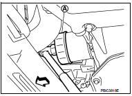
2. Using oil filter wrench [SST: KV10115801] (A), remove oil filter.
 : Vehicle front
CAUTION:
• Oil filter is provided with relief valve. Use genuine NISSAN
oil filter or equivalent.
• Be careful not to get burned when engine and engine oil may be hot.
• When removing, prepare a shop cloth to absorb any engine oil leakage or spillage.
• Completely wipe off any engine oil that adheres to engine and vehicle.
INSTALLATION
1. Remove foreign materials adhering to the oil filter installation surface.
2. Apply new engine oil to the oil seal contact surface of new oil filter.
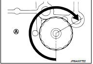
3. Screw oil filter manually until it touches the installation surface, then tighten it by 2/3 turn (A). Or tighten to specification.
Oil filter:
 : 17.7 N·m (1.8 kg-m, 13 ft-lb)
Inspection
INSPECTION AFTER INSTALLATION
1. Check the engine oil level. Refer to LU-25, "Inspection".
2. Start the engine, and check that there is no leakage of engine oil.
3. Stop the engine and wait for 10 minutes.
4. Check the engine oil level, and adjust the level. Refer to LU-25, "Inspection".
 Engine oil
Inspection
ENGINE OIL LEVEL
NOTE:
Before starting engine, put vehicle horizontally and check the engine oil level.
If engine is already started, stop
it and allow 10 minutes before checking.
...

Other materials:
System
System Diagram
System Description
DESCRIPTION
• Manual air conditioning system is controlled by each function of thermo
control amp., BCM, ECM and IPDM
E/R.
• Fan speed of blower motor is changed by the combination of fan control dial
operation and blower fan resistor
control.
CONTROL ...
Rear fog lamp
Exploded View
REMOVAL
1. Rear fog lamp
DISASSEMBLY
1. Rear fog lamp housing
2. Rear fog lamp bulb
3. Rear fog lamp bulb sock
Removal and Installation
CAUTION:
Disconnect battery negative terminal or remove the fuse.
REMOVAL
1. Insert any appropriate tool into the gap between the rea ...
B210E starter relay
DTC Logic
DTC DETECTION LOGIC
NOTE:
• If DTC B210E is displayed with DTC U1000, first perform the trouble diagnosis
for DTC U1000. Refer to
PCS-59, "DTC Logic".
• If DTC B210E is displayed with DTC B209F, first perform the trouble diagnosis
for DTC B209F. Refer to
SEC-209, " ...
