Nissan Juke Service and Repair Manual : NISSAN dynamic control system
NISSAN dynamic control system : System Diagram
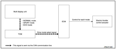
CVT models
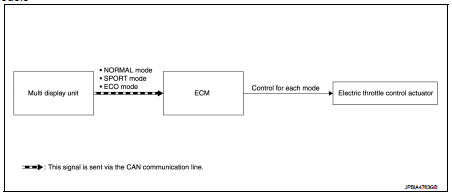
M/T models
NISSAN dynamic control system : System Description
CVT models
System Description
TCM transmits a drive mode select signal to ECM via CAN communication, according
to a NORMAL mode
signal, SPORT mode signal, or ECO mode signal received from the multi display
unit via CAN communication.
ECM controls torque and throttle opening angle characteristics appropriate for each mode, based on a received drive mode select signal.
NOTE
:
• Because of the multi display unit operation, the display may indicate that the
mode is switching. However,
the mode may not actually switch due to CAN communication error.
• When a CAN communication error occurs between ECM and TCM, the mode switches to NORMAL mode.
M/T models
System Description
ECM controls torque and throttle opening angle characteristics appropriate for
each mode, based on a NORMAL
mode signal, SPORT mode signal, or ECO mode signal received from the multi
display unit via CAN
communication.
NOTE
:
• Because of the multi display unit operation, the display may indicate that the mode is switching. However, the mode may not actually switch due to CAN communication error.
• When a CAN communication error occurs between ECM and the multi display unit, the mode switches to NORMAL mode.
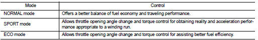
Control By Mode
 Speed limiter
Speed limiter : System Diagram
Speed limiter : System Description
INPUT/OUTPUT SIGNAL CHART
*: This signal is sent to the ECM through CAN communication line
BASIC SPEED LIMITER SYSTEM
• Spee ...
 Can communication
CAN COMMUNICATION : System Description
CAN (Controller Area Network) is a serial communication line for real time
application. It is an on-vehicle multiplex
communication line with high data commu ...
Other materials:
How to use remote keyless entry function
WARNING
• Radio waves could adversely affect electric medical equipment. Those who
use a pacemaker should contact the electric medical equipment manufacturer for the
possible influences before use.
• The Intelligent Key transmits radio waves when the buttons are pushed. The
FAA advises ...
Intake valve timing control
Intake valve timing control : System Diagram
Intake valve timing control : System Description
INPUT/OUTPUT SIGNAL CHART
SYSTEM DESCRIPTION
This mechanism hydraulically controls cam phases continuously with the fixed
operating angle of the intakevalve.
The ECM receives signals such as ...
Fuel filler lid opener
Exploded View
1. Fuel filler lid opener cable
2. Cable protector
3. Fuel filler lid lock assembly
4. Fuel filler lid assembly
5. Spring
6. Bumper rubber
: Clip
: Do not reuse
Fuel filler lid
FUEL FILLER LID : Removal and Installation
REMOVAL
1. Fully open fuel filler lid.
2. Remove ...
