Nissan Juke Service and Repair Manual : MR16DDT : Inspection and Adjustment
INSPECTION
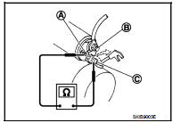
Magnetic Switch Check • Before starting to check, disconnect the battery cable from the negative terminal.
• Disconnect “M” terminal of starter motor.
1. Continuity test [between “S” terminal (A) and switch body]
B : “B” terminal
C : “M” terminal
• Replace magnetic switch if continuity does not exist.
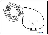
![2. Continuity test [between “S” terminal (A) and “M” terminal (C)]](images/books/335/22/index284.jpg)
2. Continuity test [between “S” terminal (A) and “M” terminal (C)]
B : “B” terminal
• Replace magnetic switch if continuity does not exist.
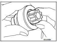
Pinion/Clutch Check
1. Inspect pinion teeth.
• Replace pinion if teeth are worn or damaged. (Also check condition of ring gear teeth.) 2. Inspect reduction gear teeth (If equipped).
• Replace reduction gear if teeth are worn or damaged. (Also check condition of armature shaft gear teeth.) 3. Check to see if pinion locks in one direction and rotates smoothly in the opposite direction.
• Replace pinion assembly if it is locked or rotated in both directions or unusual resistance is evident.
Brush Check
• Check wear of brush.
Minimum length of brush : Refer to SDS STR-35, "Starter Motor".
• Replace brush if the measurement value is less than the specified value.
Brush Spring Check
• Check brush spring tension with brush spring detached from
brush.
Spring tension (with new brush) : Refer to SDS STR-35, "Starter Motor".
• Replace brush spring if the measurement value is less than the specified value.
Brush Holder Check
1. Perform insulation test between brush holder (positive side) and
its base (negative side).
• Replace brush holder assembly if continuity does not exist.
2. Check brush to see if it moves smoothly.
• If brush holder is bent, replace it; if sliding surface is dirty, clean.
Yoke Check
Magnet is secured to yoke by bonding agent. Check magnet to see
that it is secured to yoke and for any cracks. Replace malfunctioning
parts as an assembly.
CAUTION:
Never clamp yoke in a vise or strike it with a hammer.
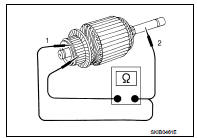
Armature Check
1. Continuity test (between two segments side by side)
• Replace armature assembly if continuity does not exist.
2. Insulation test (between each commutator bar and shaft) • Replace armature assembly if continuity exists.
3. Check commutator surface.
• Grind with No. 500 - 600 emery paper if it has a rough surface.
4. Check diameter of commutator.
Commutator minimum diameter : Refer to SDS STR-35, "Starter Motor".
• Replace armature assembly if the measurement value is less than the specified value.
5. Check depth of insulating mold from commutator surface.
• Undercut to 0.5 to 0.8 mm (0.020 to 0.031 in) if the depth is 0.2 mm (0.008 in) or less.
ADJUSTMENT
Pinion Protrusion Length Adjustment
CLEARANCE
• With pinion driven out by magnetic switch, push pinion back to
remove slack and measure clearance “L” between the front edge
of the pinion and the pinion stopper.
Clearance “L” : Refer to SDS STR-35, "Starter Motor".
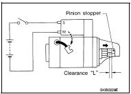
• Adjust with the adjusting plate if the measurement value is not in the specified area.
 MR16DDT : Removal and Installation
REMOVAL
1. Disconnect the battery cable from the negative terminal. Refer to PG-124,
"Removal and Installation".
2. Drain engine coolant from radiator. Refer to CO-11, "Draining&quo ...
 Service data and specifications (SDS)
Starter Motor
...
Other materials:
B263D, B263E, B263F intake door motor
DTC Logic
DTC DETECTION LOGIC
DTC CONFIRMATION PROCEDURE
1.PERFORM DTC CONFIRMATION PROCEDURE
With CONSULT-III
1. Turn ignition switch ON.
2. Select “Self Diagnostic Result” mode of “HVAC” using CONSULT-III.
3. Check DTC.
Is DTC detected?
YES >> Refer to HAC-159, "Diagnosis P ...
Vehicle security system cannot be set
Key fob
KEY FOB : Description
Armed phase is not activated when door is locked using keyfob.
NOTE:
Check that vehicle is under the condition shown in “CONDITIONS OF VEHICLE
(OPERATING CONDITIONS)”
before starting diagnosis, and check each symptom.
CONDITION OF VEHICLE (OPERATING CONDITIO ...
P0524 engine oil pressure
DTC Logic
DTC DETECTION LOGIC
NOTE:
If DTC P0524 is displayed with DTC P0520, P0075, or P0081, perform trouble
diagnosis for DTC P0520,
P0075, or P0081 first. Refer to EC-176, "DTC Logic".
DTC CONFIRMATION PROCEDURE
1.PRECONDITIONING
If DTC Confirmation Procedure has been previo ...
