Nissan Juke Service and Repair Manual : MR16DDT : Exploded View
REMOVAL
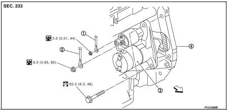
1. “S” terminal harness
2. “B” terminal harness
3. Starter motor
4. Cylinder block
 : Vehicle front
 : N·m (kg-m, in-lb)
 : N·m (kg-m, ft-lb)
DISASSEMBLY
Type: S114-902
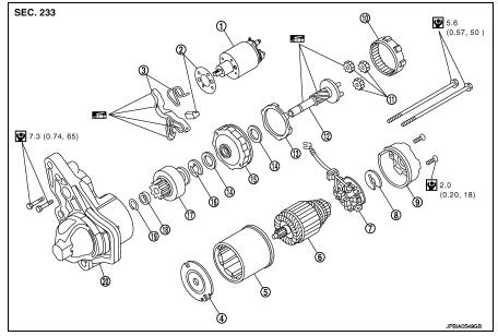
1. Magnetic switch assembly
2. Dust cover kit
3. Shift lever set
4. Center bracket (A)
5. Yoke assembly
6. Armature assembly
7. Brush holder assembly
8. Thrust washer
9. Rear cover assembly
10. Internal gear
11. Planetary gear
12. Pinion shaft
13. Packing
14. Thrust washer
15. Center bracket (P)
16. E-ring
17. Pinion assembly
18. Pinion stopper
19. Pinion stopper clip
20. Gear case assembly
 : N·m (kg-m, in-lb)
 : High-temperature grease point
Type: S114-955
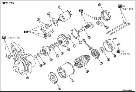
1. Magnetic switch assembly
2. Dust cover kit
3. Shift lever set
4. Center bracket (A)
5. Yoke assembly
6. Armature assembly
7. Brush holder assembly
8. Thrust washer
9. Rear cover assembly
10. Internal gear
11. Planetary gear
12. Pinion shaft
13. Packing
14. Thrust washer
15. Center bracket (P)
16. E-ring
17. Pinion assembly
18. Pinion stopper
19. Pinion stopper clip
20. Gear case assembly
 : N·m (kg-m, in-lb)
 : High-temperature grease point
NOTE
:
Apply high-temperature grease to lubricate the bearing, gears and frictional
surface when assembling the
starter.
 HR16DE : Inspection and Adjust
INSPECTION
Magnetic Switch Check
• Before starting to check, disconnect the battery cable from the negative
terminal.
• Disconnect “M” terminal of starter motor.
1. Continuity test [between “S ...
 MR16DDT : Removal and Installation
REMOVAL
1. Disconnect the battery cable from the negative terminal. Refer to PG-124,
"Removal and Installation".
2. Drain engine coolant from radiator. Refer to CO-11, "Draining&quo ...
Other materials:
B2623 inside antenna
DTC Logic
DTC DETECTION LOGIC
DTC CONFIRMATION PROCEDURE
1.PERFORM DTC CONFIRMATION PROCEDURE
1. Select “INTELLIGENT KEY” of “BCM” using CONSULT-III.
2. Select “INSIDE ANT DIAGNOSIS” in “WORK SUPPORT” mode.
3. Perform inside key antenna (“INSIDE ANT DIAGNOSIS”) on “WORK SUPPORT” of
“INTELL ...
Symptom diagnosis
COMBINATION SWITCH SYSTEM SYMPTOMS
Symptom Table
1. Perform “Data Monitor” of CONSULT-III to check for any malfunctioning
item.
2. Check the malfunction combinations.
3. Identify the malfunctioning part from the agreed combination and repair or
replace the part.
...
Continuously Variable Transmission (CVT)
The Continuously Variable Transmission (CVT) in your vehicle is electronically
controlled to produce maximum power and smooth operation.
The recommended operating procedures for this transmission are shown on the following
pages.
Follow these procedures for maximum vehicle performance and driv ...
