Nissan Juke Service and Repair Manual : Microphone signal circuit
Description
Power is supplied from NAVI control unit to microphone. The microphone transmits the sound voice to the NAVI control unit.
Diagnosis Procedure
1.CHECK CONTINUITY BETWEEN NAVI CONTROL UNIT AND MICROPHONE CIRCUIT
1. Turn ignition switch OFF.
2. Disconnect NAVI control unit connector and microphone connector.
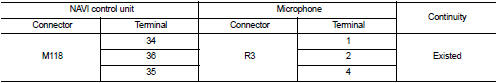
3. Check continuity between NAVI control unit harness connector and microphone harness connector.
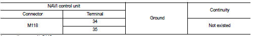
4. Check continuity between NAVI control unit harness connector and ground.
Is inspection result OK? YES >> GO TO 2.
NO >> Repair harness or connector.
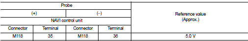
2.CHECK VOLTAGE MICROPHONE VCC
1. Connect NAVI control unit connector.
2. Turn ignition switch ON.
3. Check voltage between NAVI control unit harness connector and ground.
Is inspection result OK? YES >> GO TO 3.
NO >> Replace NAVI control unit. Refer to AV-84, "Removal and Installation".
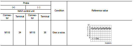
3.CHECK MICROPHONE SIGNAL
1. Turn ignition switch OFF.
2. Connect microphone connector.
3. Turn ignition switch ON.
4. Check signal between NAVI control unit harness connector.
Is inspection result OK? YES >> Replace NAVI control unit. Refer to AV-84, "Removal and Installation".
NO >> Replace microphone. Refer to AV-90, "Removal and Installation".
 Power supply and ground circuit
Navi control unit
NAVI CONTROL UNIT : Diagnosis Procedure
1.CHECK FUSE
Check for blown fuses.
Is inspection result OK?
YES >> GO TO 2.
NO >> Be sure to eliminate cause of malfunc ...
 Camera image signal circuit
Description
• The NAVI control unit supplies power to the rear view camera when receiving
a reverse signal.
• The rear view camera transmits camera images to the NAVI control unit when
power is ...
Other materials:
Air cleaner filter
Exploded View
1. Turbocharger air inlet pipe
2. Clamp
3. Air duct (suction)
4. Air mass flow sensor
5. O-ring
6. Air duct (inlet)
7. Grommet
8. Air cleaner case
9. Air cleaner filter
10. Cover
11. Holder
A. : To turbocharger
: Vehicle front
: N·m (kg-m, in-lb)
: Always replac ...
Starter motor drive control
Starter motor drive control : System Diagram
Starter motor drive control : System
DescriptionINPUT/OUTPUT SIGNAL CHART
INPUT/OUTPUT SIGNAL CHART
*: With Intelligent Key system
SYSTEM DESCRIPTION
When rapid deceleration occurs during engine runs or idle speed decreases due
to heavy load c ...
System
System Description
SYSTEM DIAGRAM
• The multi display unit transmits the operation status of the drive mode
switch to other units via CAN communication
as the mode signal (refer below).
- NORMAL: ON/OFF
- SPORT: ON/OFF
- ECO: ON/OFF
• Based on the mode signals received from TCM (CVT mod ...
