Nissan Juke Service and Repair Manual : Microphone signal circuit
Description
Power is supplied from audio unit to microphone. The microphone transmits the sound voice to the audio unit.
Diagnosis Procedure
1.CHECK CONTINUITY BETWEEN AUDIO UNIT AND MICROPHONE CIRCUIT
1. Turn ignition switch OFF.
2. Disconnect audio unit connector and microphone connector.
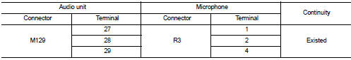
3. Check continuity between audio unit harness connector and microphone harness connector.
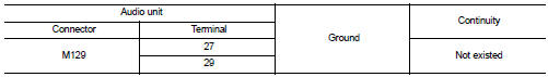
4. Check continuity between audio unit harness connector and ground.
Is inspection result OK? YES >> GO TO 2.
NO >> Repair harness or connector.
2.CHECK VOLTAGE MICROPHONE VCC
1. Connect audio unit connector.
2. Turn ignition switch ON.
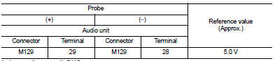
3. Check voltage between audio unit harness connector and ground.
Is inspection result OK? YES >> GO TO 3.
NO >> Replace audio unit. Refer to AV-38, "Removal and Installation".
3.CHECK MICROPHONE SIGNAL
1. Turn ignition switch OFF.
2. Connect microphone connector.
3. Turn ignition switch ON.
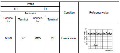
4. Check signal between audio unit harness connector.
Is inspection result OK? YES >> Replace audio unit. Refer to AV-38, "Removal and Installation".
NO >> Replace microphone. Refer to AV-43, "Removal and Installation".
 Power supply and ground circuit
AUDIO UNIT
AUDIO UNIT : Diagnosis Procedure
1.CHECK FUSE
Check for blown fuses.
Is inspection result OK?
YES >> GO TO 2.
NO >> Be sure to eliminate cause of malfunction before in ...
 Steering switch signal a circuit
Description
Transmits the steering switch signal to audio unit.
Diagnosis Procedure
1.CHECK STEERING SWITCH SIGNAL A CIRCUIT
1. Disconnect audio unit connector and spiral cable connector.
2. Chec ...
Other materials:
Connector Symbols
Most of connector symbols in wiring diagrams are shown from the terminal
side.
• Connector symbols shown from the terminal side are enclosed by
a single line and followed by the direction mark.
• Connector symbols shown from the harness side are enclosed by
a double line and followed by the ...
Diagnosis and repair workflow
Work Flow
OVERALL SEQUENCE
DETAILED FLOW
1.INTERVIEW FOR MALFUNCTION
Interview the symptom to the customer.
>> GO TO 2.
2.SYMPTOM CHECK
Check the symptom from the customer's information. Check that any symptom
occurs other than the interviewed
symptom.
Insufficient cooling/hea ...
Door request switch
Component Function Check
1.CHECK FUNCTION
1. Select “INTELLIGENT KEY” of “BCM” using CONSULT-III.
2. Select “REQ SW-DR”, “REQ SW-AS” in “DATA MONITOR” mode.
3. Check that the function operates normally according to the following
conditions.
Is the inspection result normal?
YES >> Fro ...
