Nissan Juke Owners Manual : Meters and gauges
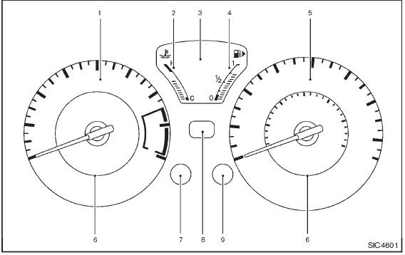
1. Tachometer
2. Engine coolant temperature gauge
3. Vehicle information display
— Odometer/twin trip odometer
— Trip computer
— Torque vectoring AWD (AWD model)
— Outside air temperature
4. Fuel gauge
5. Speedometer
6. Warning/indicator lights
7. Instrument brightness control knob
8. Continuously Variable Transmission (CVT) position indicator
9. RESET switch for trip odometer/Trip computer mode switch
: if so equipped
The needle indicators may move slightly after the ignition switch is placed in the OFF or LOCK position. This is not a malfunction.
CAUTION
• For cleaning, use a soft cloth, dampened with water. Never use a rough cloth, alcohol, benzine, thinner or any kind of solvent or paper towel with a chemical cleaning agent.
They will scratch or cause discoloration to the lens.
• Do not spray any liquid such as water on the meter lens. Spraying liquid may cause the system to malfunction.
- Speedometer and odometer
- Tachometer
- Engine coolant temperature gauge
- Fuel gauge
- Vehicle information display
- Outside air temperature
- Continuously Variable Transmission (CVT) position indicator (if so equipped)
- Trip computer
 Instrument panel
1. Meters and gauges
2. Center ventilator
3. Audio system or Navigation system
— Clock
4. Hazard warning flasher switch
5. Integrated Control System
— Drive mode
— Heater and air conditioner ...
 Speedometer and odometer
Speedometer
The speedometer indicates vehicle speed in miles per hour (MPH) and kilometers
per hour (km/h).
Odometer/twin trip odometer
The odometer 1 /twin trip odometer 2 are displayed when ...
Other materials:
Precaution for Supplemental Restraint System (SRS) "AIR BAG" and "SEAT BELT
PRE-TENSIONER"
The Supplemental Restraint System such as “AIR BAG” and “SEAT BELT PRE-TENSIONER”,
used along
with a front seat belt, helps to reduce the risk or severity of injury to the
driver and front passenger for certain
types of collision. Information necessary to service the system safely is
include ...
P1650 starter motor relay 2
Description
ECM controls ON/OFF state of the starter relay, according to the engine and
vehicle condition. Models with no
Intelligent Key System transmit a control signal directly to IPDM E/R. On the
other hand, models with the Intelligent
Key System transmit a control signal to IPDM E/R by w ...
Additional service when replacing ECM
Description
When replacing ECM, this procedure must be performed.
Work Procedure
1.PRECONDITIONING
• Connect a CONSULT-III
• Connect a battery charger
• Electric load switch is OFF
• Wait for the engine to cool [engine coolant temperature < 60?°C (140?°F) and air
temperature < 50?°C ( ...
