Nissan Juke Service and Repair Manual : Main power supply and ground circuit
Diagnosis Procedure
1.CHECK TCM POWER CIRCUIT 1
1. Turn the ignition switch OFF.
2. Disconnect the TCM connector.
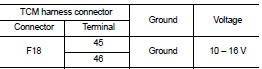
3. Check the voltage between the TCM harness connector terminals and ground.
Is the inspection result normal? YES >> GO TO 2.
NO >> GO TO 4.
2.CHECK TCM POWER CIRCUIT 2
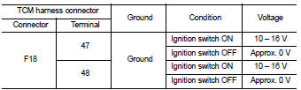
Check the voltage between the TCM harness connector terminals and ground.
Is the inspection result normal? YES >> GO TO 3.
NO >> GO TO 5.
3.CHECK TCM GROUND CIRCUIT
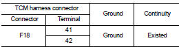
Check the continuity between TCM harness connector terminals and ground.
Is the inspection result normal? YES >> Check intermittent incident. Refer to GI-42, "Intermittent Incident".
NO >> Repair or replace the malfunctioning parts.
4.DETECT MALFUNCTION ITEMS (PART 1)
Check the following items: • Open or short circuit of the harness between battery positive terminal and TCM connectors terminals 45 and 46. Refer to PG-10, "Wiring Diagram - BATTERY POWER SUPPLY -".
• 10A fuse (No.33, fuse and fusible link block). Refer to PG-23, "Fuse and Fusible Link Arrangement".
• 10A fuse (No.36, fuse and fusible link block). Refer to PG-23, "Fuse and Fusible Link Arrangement".
Is the inspection result normal? YES >> Check intermittent incident. Refer to GI-42, "Intermittent Incident".
NO >> Repair or replace the malfunctioning parts.
5.CHECK CIRCUIT BETWEEN IPDM E/R AND TCM (PART 1)
1. Turn ignition switch OFF.
2. Disconnect the IPDM E/R connector.
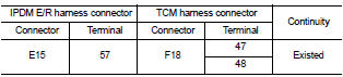
3. Check continuity between IPDM E/R harness connector terminal and TCM harness connector terminals.
Is the check result normal? YES >> GO TO 6.
NO >> Repair or replace the malfunctioning parts.
6.CHECK CIRCUIT BETWEEN IPDM E/R AND TCM (PART 2)
Check continuity between IPDM E/R harness connector terminal and ground.
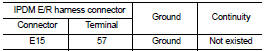
Is the check result normal? YES >> GO TO 7.
NO >> Repair or replace the malfunctioning parts.
7.DETECTION OF MALFUNCTION ITEMS (PART 2)
Check the following items: • Harness open circuit or short circuit between the ignition switch and IPDM E/R. Refer to PG-15, "Wiring Diagram - IGNITION POWER SUPPLY -".
• 10A fuse (No.55, IPDM E/R). Refer to PG-25, "Fuse, Connector and Terminal Arrangement".
• IPDM E/R
Is the check result normal? YES >> Check intermittent incident. Refer to GI-42, "Intermittent Incident".
NO >> Repair or replace the malfunctioning parts.
 P2765 clutch B speed sensor
DTC Logic
DTC DETECTION LOGIC
DTC CONFIRMATION PROCEDURE
CAUTION:
Be careful of the driving speed.
1.PREPARATION BEFORE WORK
If another "DTC CONFIRMATION PROCEDURE" occurs just befor ...
 S mode switch
Component Function Check
1.CHECK S MODE INDICATOR FUNCTION
Check S mode indicator turns ON for approx. 2 seconds when ignition switch
turns ON.
Is the inspection results normal?
YES >> G ...
Other materials:
NISSAN dynamic control system
NISSAN dynamic control system : System
Diagram
CVT models
M/T models
NISSAN dynamic control system : System
Description
CVT models
System Description
TCM transmits a drive mode select signal to ECM via CAN communication, according
to a NORMAL mode
signal, SPORT mode signal, or ECO mo ...
B1049, B1054 driver air bag module
DTC Logic
DTC DETECTION LOGIC
DTC CONFIRMATION PROCEDURE
1.CHECK SELF-DIAG RESULT
With CONSULT-III
1. Turn ignition switch ON.
2. Perform “Self Diagnostic Result” mode of “AIR BAG” using CONSULT-III.
Without CONSULT-III
1. Turn ignition switch ON.
2. Check the air bag warning lamp statu ...
Diagnosis system (ECM)
Diagnosis description
Diagnosis description : 1st Trip Detection
Logic and Two Trip Detection Logic
When a malfunction is detected for the first time, 1st trip DTC and 1st trip
Freeze Frame data are stored in the
ECM memory. The MIL will not illuminate at this stage. <1st trip>
If the s ...
