Nissan Juke Service and Repair Manual : Magnet clutch
Component Function Check
1.CHECK MAGNET CLUTCH OPERATION
Perform auto active test of IPDM E/R. Refer to PCS-12, "Diagnosis Description" (with Intelligent Key) or PCS- 43, "Diagnosis Description" (without Intelligent Key).
Does it operate normally? YES >> INSPECTION END
NO >> Refer to HAC-83, "Diagnosis Procedure".
Diagnosis Procedure
1.CHECK FUSE
1. Turn ignition switch OFF.
2. Check 10A fuse (No. 49, located in IPDM E/R).
NOTE
:
Refer to PG-25, "Fuse, Connector and Terminal Arrangement".
Is the inspection result normal? YES >> GO TO 2.
NO >> Replace the blown fuse after repairing the affected circuit if a fuse is blown.
2.CHECK MAGNET CLUTCH
1. Disconnect compressor connector.
2. Directly apply battery voltage to the magnet clutch. Check for operation visually and by sound.
Does it operate normally? YES >> GO TO 3.
NO >> Replace magnet clutch. Refer to HA-88, "MAGNET CLUTCH : Removal and Installation of Compressor Clutch".
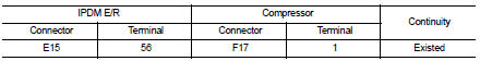
3.CHECK MAGNET CLUTCH POWER SUPPLY CIRCUIT FOR OPEN
1. Disconnect IPDM E/R connector.
2. Check continuity between IPDM E/R harness connector and compressor harness connector.
Is the inspection result normal? YES >> Replace IPDM E/R. Refer to PCS-34, "Removal and Installation" (with Intelligent Key) or PCS-63, "Removal and Installation" (without Intelligent Key).
NO >> Repair harness or connector.
 Blower motor
Diagnosis Procedure
1.CHECK FUSE
1. Turn ignition switch OFF.
2. Check following fuses.
- 10A fuse [No. 15, located in fuse block (J/B)]
- 15A fuses [Nos. 14 and 16, located in fuse block (J/B) ...

Other materials:
Push-button ignition switch does not operate
Description
Check that vehicle is under the condition shown in “Conditions of vehicle”
before starting diagnosis, and check
each symptom.
NOTE:
The engine start function, door lock function, power distribution system, and
NATS-IVIS/NVIS in the Intelligent
Key system are closely related to ...
Trouble diagnosis
System Diagram
Condition of Error Detection
DTC (e.g. U1000 and U1001) of CAN communication is indicated on SELF-DIAG
RESULTS on CONSULT-III
if a CAN communication signal is not transmitted or received between units for 2
seconds or more.
CAN COMMUNICATION SYSTEM ERROR
• CAN communicati ...
Push-button ignition switch position indicator
Description
Push-button ignition switch changes the power supply position.
BCM maintains the power supply position status.
BCM changes the power supply position with the operation of the push-button
ignition switch.
Component Function Check
1.CHECK FUNCTION
Check push-button ignition swi ...
