Nissan Juke Service and Repair Manual : Lower link
Exploded View
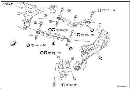
1. Rear suspension member
2. Adjusting bolt
3. Upper link
4. Eccentric disk
5. Lower link
6. Suspension arm bracket
7. Suspension arm
 : Vehicle front
 : Always replace after every
disassembly.
 : N·m (kg-m, ft-lb)
Removal and Installation
REMOVAL
1. Remove tires. Refer to WT-7, "Removal and Installation".
2. Set jack under suspension arm.
CAUTION:
• Never damage the suspension arm with a jack.
• Check the stable condition when using a jack
.
3. Remove stabilizer link. Refer to RSU-34, "Removal and Installation".
4. Remove eccentric disc, adjusting bolt, mounting bolt, and nut, then remove lower link.
5. Perform inspection after removal. Refer to RSU-31, "Inspection".
INSTALLATION
Note the following, and install in the reverse order of removal.
• Perform final tightening of rear suspension member and axle installation position (rubber bushing), under unladen conditions with tires on level ground.
• Never reuse lower link mounting nut.
• Perform inspection after installation. Refer to RSU-31, "Inspection".
Inspection
INSPECTION AFTER REMOVAL
Check lower link and bushing for any deformation, cracks, or damage. Replace it if necessary.
INSPECTION AFTER INSTALLATION
1. Check wheel alignment. Refer to RSU-20, "Inspection".
2. Adjust neutral position of steering angle sensor. Refer to BRC-149, "Work Procedure" (With ESP).
 Suspension arm
Exploded View
1. Rear suspension member
2. Adjusting bolt
3. Upper link
4. Eccentric disk
5. Lower link
6. Suspension arm bracket
7. Suspension arm
: Vehicle front
: Always replace afte ...
 Upper link
Exploded View
1. Rear suspension member
2. Adjusting bolt
3. Upper link
4. Eccentric disk
5. Lower link
6. Suspension arm bracket
7. Suspension arm
: Vehicle front
: Always replace afte ...
Other materials:
Structure and operation
Sectional View
1. Transfer cover
2. Ring gear shaft
3. Companion flange
4. Drive pinion
5. Ring gear
6. Transfer case
Operation Principle
POWER TRANSFER DIAGRAM
1. Engine
2. Transaxle
3. Transfer
4. Propeller shaft
5. Electric controlled coupling
6. Rear final drive
ELECTR ...
Key ID warning does not operate
Diagnosis Procedure
1.CHECK DTC WITH BCM AND COMBINATION METER
Check that DTC is not detected with BCM and combination meter.
Is the inspection result normal?
YES >> GO TO 2.
NO-1 >> Refer to BCS-67, "DTC Index". (BCM)
NO-2 >> Refer to MWI-36, "DTC Index&qu ...
Precaution Necessary for Steering Wheel Rotation after Battery Disconnect
NOTE:
• Before removing and installing any control units, first turn the ignition
switch to the LOCK position, then disconnect
both battery cables.
• After finishing work, confirm that all control unit connectors are connected
properly, then re-connect both
battery cables.
• Always use CONS ...
