Nissan Juke Service and Repair Manual : Liquid Gasket
REMOVAL OF LIQUID GASKET SEALING
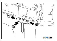
• After removing mounting nuts and bolts, separate the mating surface using the seal cutter [SST: KV10111100] (A) and remove old liquid gasket sealing.
CAUTION:
Be careful not to damage the mating surface
s.
• Tap the seal cutter [SST: KV10111100] to insert it (B), and then slide it (C) by tapping on the side as shown in the figure.
• In areas where the seal cutter [SST: KV10111100] is difficult to use, lightly tap the parts using a plastic hammer to remove it.
CAUTION:
If for some unavoidable reason tool such as a screwdriver is
used, be careful not to damage the mating surfaces.
LIQUID GASKET APPLICATION PROCEDURE
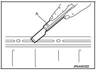
1. Using a scraper (A), remove old liquid gasket adhering to the liquid gasket application surface and the mating surface.
• Remove liquid gasket completely from the groove of the liquid gasket application surface, mounting bolts, and bolt holes.
2. Wipe the liquid gasket application surface and the mating surface with white gasoline (lighting and heating use) to remove adhering moisture, grease and foreign materials.
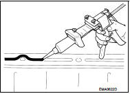
3. Attach liquid gasket tube to the tube presser (commercial service tool).
Use Genuine Liquid gasket or equivalent.
4. Apply liquid gasket without gaps to the specified location according to the specified dimensions.
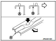
• If there is a groove for liquid gasket application, apply liquid gasket to the groove.
• As for bolt holes (B), normally apply liquid gasket inside the holes. Occasionally, it should be applied outside the holes.
Check to read the text of this manual.
A : Groove
 : Inside
• Within five minutes of liquid gasket application, install the mating component.
• If liquid gasket protrudes, wipe it off immediately.
• Do not retighten mounting bolts or nuts after the installation.
• After 30 minutes or more have passed from the installation, fill engine oil and engine coolant.
CAUTION
:
If there are specific instructions in this manual, observe them.
 Precaution
...

Other materials:
Wiring diagram
HEATED SEAT SYSTEM
Wiring Diagram
For connector terminal arrangements, harness layouts, and alphabets in a
(option abbreviation; if not
described in wiring diagram), refer to GI-12, "Connector Information/Explanation
of Option Abbreviation".
...
U1119 lost comm (multi-display)
Description
CAN (Controller Area Network) is a serial communication line for real-time
application. It is an on-vehicle multiplex
communication line with high data communication speed and excellent malfunction
detection ability.
Many electronic control units are equipped onto a vehicle, and ...
Drive information
While in the Drive mode, push the Drive information button to display elapsed
time, average speed and trip distance. Pressing the Drive information button a second
time will display the G (gravity)-Force screen.
Elapsed time
The elapsed time shows the time since the last reset.
Average spee ...
