Nissan Juke Service and Repair Manual : L terminal circuit (open)
Description
The “L” terminal circuit controls the charge warning lamp. The charge warning lamp illuminates when the ignition switch is set to ON or START. When the alternator is providing sufficient voltage with the engine running, the charge warning lamp will go off. If the charge warning lamp illuminates with the engine running, a malfunction is indicated.
Diagnosis Procedure
1.CHECK “L” TERMINAL CONNECTION
1. Turn ignition switch OFF.
2. Check if “L” terminal is clean and tight.
Is the inspection result normal? YES >> GO TO 2.
NO >> Repair “L” terminal connection.
2.CHECK “L” TERMINAL CIRCUIT (OPEN)
1. Disconnect alternator connector.
2. Apply ground to alternator harness connector terminal.
3. Check condition of the charge warning lamp with the ignition switch in the ON position.
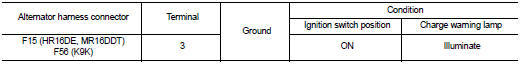
Does it illuminate? YES >> “L” terminal circuit is normal. Refer to CHG-12, "GASOLINE ENGINE MODELS : Work Flow" (gasoline engine models) or CHG-15, "DIESEL ENGINE MODELS : Work Flow" (diesel engine models).
NO >> GO TO 3.
3.CHECK HARNESS CONTINUITY (OPEN CIRCUIT)
1. Disconnect the battery cable from the negative terminal.
2. Disconnect the combination meter connector.
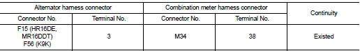
3. Check continuity between alternator harness connector and combination meter harness connector.
Is the inspection result normal? YES >> GO TO 4.
NO >> Repair the harness or connector.
4.CHECK HARNESS CONTINUITY (OPEN CIRCUIT)
Check continuity between combination meter harness connector M34 terminal 28 and 10A fuse [No.5 located in the fuse block (J/B)].
Does continuity exist? YES >> GO TO 5.
NO >> Repair the harness.
5.CHECK POWER SUPPLY CIRCUIT
1. Connect the battery cable to the negative terminal.
2. Check voltage between combination meter harness connector and ground.
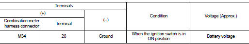
Is the inspection result normal? YES >> Replace combination meter.
NO >> Inspect the power supply circuit. Refer to PG-15, "Wiring Diagram - IGNITION POWER SUPPLY - ".
 B terminal circuit
Description
“B” terminal circuit supplies power to charge the battery and to operate the
vehicle’s electrical system.
Diagnosis Procedure
1.CHECK “B” TERMINAL CONNECTION
1. Turn ignition switch ...
 L terminal circuit (short)
Description
The “L” terminal circuit controls the charge warning lamp. The charge warning
lamp illuminates when the ignition
switch is set to ON or START. When the alternator is providing sufficie ...
Other materials:
B2196 dongle unit
Description
BCM performs ID verification between BCM and dongle unit.
When verification result is OK, BCM permits cranking.
DTC Logic
DTC DETECTION LOGIC
DTC CONFIRMATION PROCEDURE
1.PERFORM DTC CONFIRMATION PROCEDURE
1. Turn ignition switch ON.
2. Turn ignition switch OFF.
3. Turn igni ...
P0234 TC system
DTC Logic
DTC DETECTION LOGIC
NOTE:
If DTC P0234 is displayed with DTC P0237 or P0238, first perform the trouble
diagnosis for DTC P0237 or
P0238. Refer to EC-260, "DTC Logic".
DTC CONFIRMATION PROCEDURE
1.PERFORM COMPONENT FUNCTION CHECK
Perform component function check. Refer ...
Front door
Exploded View
1. Front door panel
2. Grommet
3. TORX bolt
4. Door striker
5. Door pad
6. Bumper rubber
7. Door check link
8. Door hinge (lower)
9. Door hinge (upper)
10. Grommet
: Do not reuse
: N·m (kg-m, in-lb)
: N·m (kg-m, ft-lb)
: Body grease
Door assembly
DOOR ASSEMBLY : ...
