Nissan Juke Service and Repair Manual : Keyfob battery
Exploded View
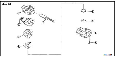
1. Upper case
2. Key
3. Switch cover
4. Switch rubber
5. Board surface
6. Battery
7. plate
8. Lower case
9. Screw
Removal and Installation
REMOVAL
1. Remove screw (9) on the rear of keyfob.
2. Place the key with the lower case (8) facing up. Set a screw-driver wrapped with tape between upper case (1) and lower case (8) and then separate the lower case (8) from the upper case (1).
CAUTION:
• Do not touch the circuit board or battery terminal.
• The keyfob is water-resistant. However, if it does get wet, immediately wipe it dry.
3. When replacing the circuit board assembly, remove circuit board assembly from the upper case (1).
[Circuit board assembly: Switch rubber (4) + Board surface (5)]
CAUTION:
Do not touch the printed circuits directly.
4. Remove the battery (6) from the lower case (8) and replace it.
Battery replacement : Coin-type lithium battery (CR1620)
CAUTION:
When replacing battery, keep dirt, grease, and other foreign materials off the
electrode contact
area.
5. After replacement, fit the lower and upper cases together, part (4), (7) and tighten with the screw.
CAUTION:
After replacing the battery, Be sure to check that door locking operates
normally using the keyfob.
Refer to DLK-528, "Component Function Check".
INSTALLATION
Install in the reverse order of removal.
 Remote keyless entry receiver
Removal and Installation
REMOVAL
1. Remove the glove box assembly. Refer to IP-13, "Removal and
Installation".
2. Remove the remote keyless entry receiver (1) mounting bolt (A),
and th ...

Other materials:
Additional service when replacing
ECM
Description
When replacing ECM, this procedure must be performed.
Work Procedure
1.PERFORM INITIALIZATION OF NATS SYSTEM AND REGISTRATION OF ALL NATS
IGNITION KEY IDS
Refer to SEC-50, "ECM : Work Procedure".
>> GO TO 2.
2.PERFORM ACCELERATOR PEDAL RELEASED POSITION LEARNIN ...
U0141 lost communication (BCM A)
Description
CAN (Controller Area Network) is a serial communication line for real-time
application. It is an on-vehicle multiplex
communication line with high data communication speed and excellent malfunction
detection ability.
Many electronic control units are equipped onto a vehicle, and ...
Removal and Installation Procedure for CVT Unit Connector
REMOVAL
• Rotate bayonet ring (A) counterclockwise. Pull out CVT unit harness
connector (B) upward and remove it.
INSTALLATION
1. Align marking (A) on CVT unit harness connector terminal with
marking (B) on bayonet ring. Insert CVT unit harness connector.
2. Rotate bayonet ring clockwise.
...
