Nissan Juke Service and Repair Manual : Interior room lamp control circuit
Description
Controls each interior room lamp (ground side) by PWM signal.
NOTE
:
PWM signal control period is approximately 250 Hz (in the gradual
brightening/dimming).
Component Function Check
CAUTION:
Before performing the diagnosis, check that the following are normal.
• Interior room lamp power supply • Map lamp bulb
1.CHECK INTERIOR ROOM LAMP CONTROL FUNCTION
 CONSULT-III ACTIVE TEST
1. Switch the map lamp switch to DOOR.
2. Turn ignition switch ON.
3. Select “INT LAMP” of BCM (INT LAMP) active test item.
4. With operating the test items, check that each interior room lamp turns ON/OFF (gradual brightening/dimming).
On : Interior room lamp gradual brightening Off : Interior room lamp gradual dimming
Does the interior room lamp turns ON/OFF (gradual brightening/dimming)? YES >> Interior room lamp control circuit is normal.
NO >> Refer to INL-30, "Diagnosis Procedure".
Diagnosis Procedure
1.CHECK INTERIOR ROOM LAMP CONTROL OUTPUT
 CONSULT-III ACTIVE TEST
1. Turn ignition switch OFF.
2. Remove all the bulbs of map lamp.
3. Turn ignition switch ON.
4. Select “INT LAMP” of BCM (INT LAMP) active test item.
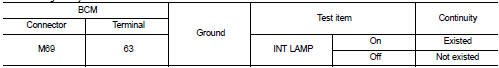
5. With operating the test item, check continuity between BCM harness connector and ground.
With Intelligent Key
Without Intelligent Key
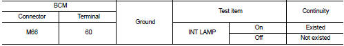
Is the inspection result normal? YES >> GO TO 2.
Fixed ON>>GO TO 3.
Fixed OFF>>Replace BCM. Refer to BCS-93, "Removal and Installation".
2.CHECK INTERIOR ROOM LAMP CONTROL OPEN CIRCUIT
1. Turn ignition switch OFF.
2. Disconnect BCM connector, map lamp connector.
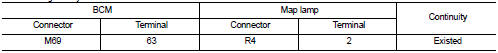
3. Check continuity between BCM harness connector and map lamp harness connector.
With Intelligent Key
Without Intelligen
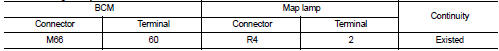
Is the inspection result normal? YES >> Replace map lamp.Refer to INL-37, "Removal and Installation".
NO >> Repair or replace harnesses.
3.CHECK INTERIOR ROOM LAMP CONTROL SHORT CIRCUIT
1. Turn ignition switch OFF.
2. Disconnect BCM connector and map lamp connector.
3. Check continuity between BCM harness connector and ground.
With Intelligent Key
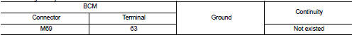
Without Intelligent Key
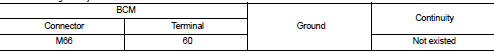
Is the inspection result normal? YES >> Replace BCM. Refer to BCS-93, "Removal and Installation".
NO >> Repair or replace harnesses.
 Interior room lamp power supply circuit
Description
Provides the interior room lamp power supply. Also cuts the power supply when
the interior room lamp battery
saver activating.
Component Function Check
1.CHECK INTERIOR ROOM LAMP POW ...
 Luggage room lamp circuit
Description
Controls the luggage room lamp (ground side) to turn the luggage room lamp ON
and OFF.
Diagnosis Procedure
CAUTION:
Before performing the diagnosis, check that the following are norm ...
Other materials:
Trouble diagnosis - specification valuE
Description
The specification (SP) value indicates the tolerance of the value that is
displayed in “SPEC” of “DATA MONITOR”
mode of CONSULT-III during normal operation of the Engine Control System. When
the value in “SPEC”
of “DATA MONITOR” mode is within the SP value, the Engine Control Syst ...
Ignition coil, spark plug and rocker cover
Exploded View
1. Rocker cover protector
2. O-ring
3. PCV control valve
4. PCV hose
5. Clamp
6. Rocker cover gasket
7. Rocker cover
8. Clamp
9. PCV hose
10. Oil filler cap
11. Spark plug
12. Ignition coil
A. To air duct assembly
B.Tightening must be done following
the instal ...
Door lock operation warning does not operate
Diagnosis Procedure
1.CHECK DOOR LOCK FUNCTION
Check door lock function.
Does door lock/unlock using door request switch?
YES >> GO TO 2.
NO >> Refer to DLK-85, "Component Function Check".
2.CHECK INTELLIGENT KEY WARNING BUZZER
Check Intelligent Key warning buzzer. ...
