Nissan Juke Service and Repair Manual : Intake valve timing control
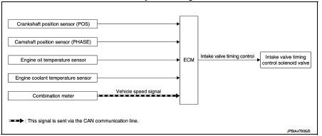
Intake valve timing control : System Diagram
Intake valve timing control : System Description
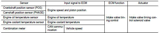
INPUT/OUTPUT SIGNAL CHART
SYSTEM DESCRIPTION
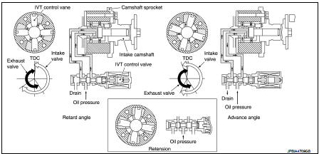
This mechanism hydraulically controls cam phases continuously with the fixed operating angle of the intakevalve.
The ECM receives signals such as crankshaft position, camshaft position, engine speed, and engine coolanttemperature.
Then, the ECM sends ON/OFF pulse duty signals to the intake valve timing (IVT) control solenoid valve depending on driving status. This makes it possible to control the shut/open timing of the intake valve to increase engine torque in low/mid speed range and output in high-speed range.
 Electric ignition system
Electric ignition system : System Diagram
Electric ignition system : System Description
INPUT/OUTPUT SIGNAL CHART
*1: CVT models
*2: M/T models
*3: ECM determines the start signa ...
 Exhaust valve timing control
Exhaust valve timing control : System Diagram
Exhaust valve timing control: System Description
INPUT/OUTPUT SIGNAL CHART
SYSTEM DESCRIPTION
This mechanism hydraulically controls cam phases c ...
Other materials:
Commercial Service Tools
HFC-134a (R-134a) Service Tool and Equipment
• Never mix HFC-134a (R-134a) refrigerant and/or its specified lubricant with
CFC-12 (R-12) refrigerant and/
or its lubricant.
• Separate and non-interchangeable service equipment must be used for handling
each type of refrigerant/
lubricant.
• R ...
Security indicator lamp
Component Function Check
1.CHECK FUNCTION
1. Perform “THEFT IND” in “ACTIVE TEST” mode of “IMMU” of “BCM” using
CONSULT-III.
2. Check security indicator lamp operation.
Is the inspection result normal?
YES >> INSPECTION END
NO >> Go to SEC-159, "Diagnosis Procedure".
...
System
System Diagram
System Description
DESCRIPTION
• Manual air conditioning system is controlled by each function of thermo
control amp., BCM, ECM and IPDM
E/R.
• Fan speed of blower motor is changed by the combination of fan control dial
operation and blower fan resistor
control.
CONTROL ...
