Nissan Juke Service and Repair Manual : Intake manifold
Exploded View
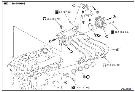
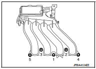
1. EVAP canister purge volume control
solenoid valve
2. Hose clamp
3. Vacuum hose
4. Intake manifold support
5. Gasket
6. Intake manifold
7. Electric throttle control actuator
8. Gasket
A. To air cleaner
B. To centralized under-floor piping
C. To brake booster
D. To rocker cover
 : Always replace after every
disassembly.
 : N·m (kg-m, in-lb)
 : N·m (kg-m, ft-lb)
Removal and Installation
REMOVAL
1. Drain engine coolant. Refer to CO-11, "Draining".
CAUTION:
• Perform this step when the engine is cold.
• Never spill engine coolant on drive belt.
2. Remove air duct (inlet) and air duct assembly. Refer to EM-161, "Exploded View".
3. Remove reservoir tank.
4. Pull out oil level gauge.
CAUTION:
Cover the oil level gauge guide openings to avoid entry of foreign materials.
5. Disconnect water hoses from electric throttle control actuator as follows: • Drain engine coolant from radiator or attach plug to prevent engine coolant leakage when engine coolant is not drained. Refer to CO-11, "Draining".
CAUTION:
Perform this step when the engine is cold.
6. Remove electric throttle control actuator.
CAUTION:
• Handle carefully to avoid any shock to electric throttle control actuator.
• Never disassemble electric throttle control actuator.
7. Disconnect harness connector and vacuum hose from purge control solenoid valve.
CAUTION:
Never impact it
.
8. Disconnect vacuum hose for brake booster from intake manifold.
9. Remove mounting bolts of intake manifold. (The joint of intake manifold and
rocker cover.)
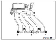
10. Loosen mounting bolts in reverse order as shown in the figure.
CAUTION:
Cover engine openings to avoid entry of foreign materials.
11. Remove intake manifold.
12. Remove EVAP canister purge volume control solenoid valve from intake manifold if necessary.
CAUTION:
Never impact it.
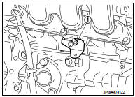
13. Remove intake manifold support (1) if necessary.
CAUTION:
The intake manifold support functions as a guide for installing
the intake manifold.
INSTALLATION
Note the following, and install in the reverse order of removal.
Intake Manifold
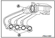
1. Install the gasket to the intake manifold.
• Align the protrusions used for checking gasket installation condition with the clearance grooves (A) of the intake manifold mounting groove.
NOTE
:
Gasket for electronically-controlled throttle can be installed
when the electronically-controlled throttle is installed.
2. Place the intake manifold into the installation position.
CAUTION
:
Check that the oil level gauge guide is not detached from the securing clip
of the water inlet due to
interference of intake manifold.
3. Tighten bolts in the numerical order as shown in the figure.
4. Tighten mounting bolts of intake manifold. (The joint of intake manifold and rocker cover.) Electric Throttle Control Actuator • Tighten bolts of electric throttle control actuator equally and diagonally in several steps.
• Perform “Throttle Valve Closed Position Learning” after repair when removing harness connector of the electric throttle control actuator. Refer to EC-543, "Description".
• Perform “Throttle Valve Closed Position Learning” and “Idle Air Volume Learning” after repair when replacing electric throttle control actuator. Refer to EC-544, "Description"
 Air cleaner and air duct
Exploded View
1. Hose clamp
2. PCV hose
3. Hose clamp
4. Air cleaner filter
5. Air cleaner filter case
6. Grommet
7. Inlet air duct (lower)
8. Grommet
9. Inlet air duct (upper)
10. ...
 Exhaust manifold
Exploded View
1. Exhaust manifold cover
2. Harness bracket
3. Air fuel ratio sensor 1
4. Exhaust manifold stay
5. Heat insulator
6. Exhaust manifold
7. Exhaust manifold cover
8. Gasket ...
Other materials:
ASCD main switch
Component Function Check
1.CHECK ASCD MAIN SWITCH FUNCTION
With CONSULT-III
1. Turn ignition switch ON.
2. Select “ENGINE” using CONSULT-III.
3. Select “MAIN SW” in “DATA MONITOR” mode.
4. Check “MAIN SW” indication under the following condition.
Without CONSULT-III
1. Turn ignition switch ...
Security indicator lamp
Component Function Check
1.CHECK FUNCTION
1. Perform “THEFT IND” in the “ACTIVE TEST” mode of “BCM” using
CONSULT-III.
2. Check security indicator lamp operation.
Is the inspection result normal?
YES >> INSPECTION END
NO >> Go to SEC-227, "Diagnosis Procedure".
Diagn ...
Normal operating condition
Description
FUEL CUT CONTROL (AT NO LOAD AND HIGH ENGINE SPEED)
If the engine speed is above 2,400 rpm under no load (for example, the shift
lever position is neutral and
engine speed is over 2,400 rpm) fuel will be cut off after some time. The exact
time when the fuel is cut off varies
base ...
