Nissan Juke Service and Repair Manual : Inspection
INSPECTION AFTER REMOVAL
Appearance
Check the propeller shaft for bend and damage. If damage is detected, replace
propeller shaft assembly.
Propeller Shaft Runout
Check propeller shaft runout at measuring points with a dial indicator.
If runout exceeds specifications, replace propeller shaft assembly.
Propeller shaft runout : Refer to DLN-125, "Propeller Shaft Runout".
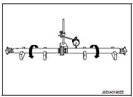
• Propeller shaft runout measuring point (Point “
”)
 : Front
Dimension A: 542 mm (21.34 in) B: 516.5 mm (20.33 in)
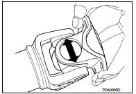
Journal Axial Play
As shown in the figure, while fixing yoke on one side, check axial
play of joint. If it is outside the standard, replace propeller shaft
assembly.
Journal axial play : Refer to DLN-125, "Journal Axial Play".
CAUTION:
Never disassemble joints.
Center Bearing
Check center bearing for noise and damage. If noise or damage is detected,
replace propeller shaft assembly.
CAUTION:
Never disassemble center bearing.
INSPECTION AFTER INSTALLATION
After assembly, perform a driving test to check propeller shaft vibration. If vibration occurred, separate propeller shaft from final drive or transfer. Reinstall companion flange by changing the phase between companion flange and propeller shaft by the one bolt hole at a time. Then perform driving test and check propeller shaft vibration again at each point.
 Removal and Installation
REMOVAL
1. Shift the transaxle to the neutral position, and then release the parking
brake.
2. Put matching marks on propeller shaft flange yoke and final drive companion
flanges.
CAUTION:
F ...

Other materials:
Symptom diagnosis
SYSTEM SYMPTOM
Symptom Table
The diagnostics item numbers show the sequence for inspection. Inspect in
order from item 1.
...
Automatic air conditioner (with Integrated Control System)
1. AUTO button/Temperature control dial
2. OFF button
3. A/C button
4. CLIMATE button
5. Display screen
6. Air flow control buttons
7. Fan speed control dial
8. Front defroster button
9. Air intake button (Outside air circulation
/Air recirculation
)
10. Rear window defroster button ( ...
System
System Description
• The system switches fluid pressure of each brake caliper to increase, to
hold or to decrease according to
signals from control unit in ABS actuator and electric unit (control unit). This
control system is applied to ESP
function, TCS function, ABS function, EBD function a ...
