Nissan Juke Service and Repair Manual : Ignition coil, spark plug and rocker cover
Exploded View
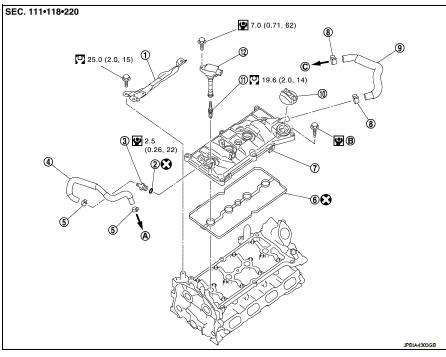
1. Rocker cover protector
2. O-ring
3. PCV control valve
4. PCV hose
5. Clamp
6. Rocker cover gasket
7. Rocker cover
8. Clamp
9. PCV hose
10. Oil filler cap
11. Spark plug
12. Ignition coil
A. To air duct assembly B.Tightening must be done following the installation procedure.
Refer to EM-53
C. To turbocharger inlet tube
 : N·m (kg-m, ft-lb)
 : N·m (kg-m, in-lb)
 : Always replace after every
disassembly.
Removal and Installation
REMOVAL
1. Drain engine coolant. Refer to CO-11, "Draining".
2. Remove engine cover. Refer to EM-25, "Exploded View".
3. Remove intake manifold. Refer to EM-28, "Exploded View".
4. Remove air inlet tube assembly. Refer to EM-31, "Exploded View".
5. Remove PCV hose.
6. Remove rocker cover protector.
7. Disconnect ignition coil harness connector, and them remove ignition coil.
CAUTION:
• Never drop or shock ignition coil.
• Never disassemble ignition coil.
8. Move ignition harness.
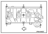
9. Remove rocker cover.
• Loosen bolts in reverse order shown in the figure.
 : Engine front
10. Remove PCV valve and PCV hose, if necessary.
11. Remove rocker cover gasket from rocker cover.
INSTALLATION
1. Install the rocker cover gasket to rocker cover.
CAUTION:
Check the gasket is not dropped.
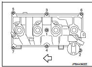
2. Install rocker cover.
• Tighten bolts in two steps separately in numerical order as shown in the figure.
: Engine front
1st step : 1.96 N·m (0.20 kg-m,
17 in-lb)
2nd step : 8.33 N·m (0.85 kg-m, 74
in-lb)
3. Install in the reverse order of removal, for the rest of parts.
 Fuel injector and fuel tube
Exploded View
1. Holder
2. Seal ring (white)
3. Backup ring
4. O-ring (blue)
5. Fuel injector
6. Stud bolt
7. Fuel tube assembly
8. Fuel tube insulator
9. Fuel tube protector
10. Fu ...
 Unit removal and installation
Engine assembly
2WD
2WD : Exploded View
1. Washer
2. Upper torque rod (RH)
3. Engine mounting insulator (RH)
4. Rear torque rod bracket
5. Rear torque rod
6. Engine mounting insulator (L ...
Other materials:
Precaution Necessary for Steering Wheel Rotation
after Battery Disconnect
NOTE:
• Before removing and installing any control units, first turn the ignition
switch to the LOCK position, then disconnect
both battery cables.
• After finishing work, confirm that all control unit connectors are connected
properly, then re-connect both
battery cables.
• Always use CONS ...
Performance test
Inspection
INSPECTION PROCEDURE
1. Connect recovery/recycling/recharging equipment (for HFC-134a) or manifold
gauge.
2. Start the engine, and set to the following condition.
Test condition
3. Maintain test condition until A/C system becomes stable. (Approximately 10
minutes)
4. Check t ...
Nats antenna AMP
Removal and Installation
REMOVAL
1. Remove the cluster lid A. Refer to IP-13, "Removal and Installation".
2. Remove the NATS antenna amp.
1. Disengage the NATS antenna amp. (1) fixing pawls using
minus driver etc.
2. Pull NATS antenna amp. to remove it from push-button ignition
sw ...
