Nissan Juke Service and Repair Manual : HR16DE : Removal and Installation
REMOVAL
1. Disconnect the battery cable from the negative terminal. Refer to PG-124, "Removal and Installation".
2. Remove radiator reservoir tank. Refer to CO-17, "Exploded View".
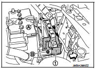
3. Disconnect harness connectors (1) from battery terminal with fusible link.
4. Remove harness fixing clips (A) from F/L·fuse holder bracket.
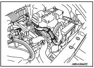
5. Remove harness fixing clips (A) from F/L·fuse holder bracket.
6. Disconnect harness connector (1) from ECM.
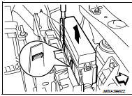
7. Disengage pawl using a flat-bladed screwdriver (A). Remove F/ L·fuse holder.
 : Vehicle front
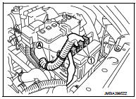
8. Move F/L·fuse holder and harness to a location where they do not inhibit work.
9. Remove harness fixing clips (A) from F/L·fuse holder bracket.
10. Remove mounting bolt (A) and nut (B) of F/L·fuse holder bracket (1), and then remove F/L·fuse holder bracket.
 : Vehicle front
11. Remove mounting bolt (A), and then move water hose (1) and heater thermostat (2) to a location where they do not inhibit work (CVT models).
 : Vehicle front
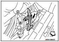
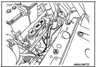
12. Remove “B” terminal nut and “B” terminal harness.
13. Remove “S” terminal nut and “S” terminal harness.
14. Remove starter motor mounting bolts.
15. Remove starter motor towards vehicle upper.
INSTALLATION
Note the following item, and then install in the reverse order of removal.
CAUTION:
Be careful to tighten “B” terminal nut to the specified torque.
 HR16DE : Exploded View
REMOVAL
1. Cylinder block
2. “B” terminal harness
3. “S” terminal harness
4. Starter motor
: Vehicle front
: N·m (kg-m, in-lb)
: N·m (kg-m, ft-lb)
DISASSEMBLY
Type: M000T32172ZE
1. “M” ...
 HR16DE : Inspection and Adjust
INSPECTION
Magnetic Switch Check
• Before starting to check, disconnect the battery cable from the negative
terminal.
• Disconnect “M” terminal of starter motor.
1. Continuity test [between “S ...
Other materials:
Air breather hose
Removal and Installation
REMOVAL
1. Remove air cleaner case. Refer to EM-26, "Removal and Installation".
2. Remove clip from bracket.
3. Remove air breather hose from transaxle assembly.
INSTALLATION
Note the following, and install in the reverse order of removal.
CAUTION:
Chec ...
Diagnosis system (BCM) (with intelligent key system)
Common item
COMMON ITEM : CONSULT-III Function (BCM - COMMON ITEM)
APPLICATION ITEM
CONSULT-III performs the following functions via CAN communication with BCM.
SYSTEM APPLICATION
BCM can perform the following functions for each system.
NOTE:
It can perform the diagnosis modes except the fo ...
System
Can communication system
CAN COMMUNICATION SYSTEM : System Diagram
CAN COMMUNICATION SYSTEM : System Description
Description
• CAN (Controller Area Network) is a serial communication line for real time
application. It is an on-vehicle
multiplex communication line with high data communicatio ...
