Nissan Juke Service and Repair Manual : Hood switch
Component Function Check
1.CHECK FUNCTION
1. Select “HOOD SW” in “Data Monitor” mode of “IPDM E/R” using CONSULT-III.
2. Check “HOOD SW” indication under the following condition.
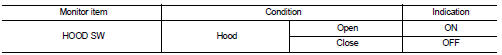
Is the indication normal? YES >> Hood switch is OK.
NO >> Go to SEC-223, "Diagnosis Procedure".
Diagnosis Procedure
1.CHECK HOOD SWITCH SIGNAL CIRCUIT 1
1. Turn ignition switch OFF.
2. Disconnect hood switch connector.
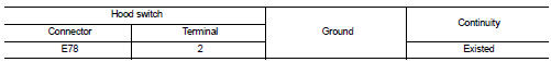
3. Check voltage between hood switch harness connector and ground.
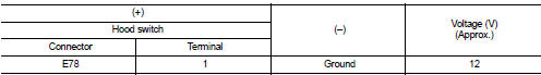
Is the inspection result normal? YES >> GO TO 3.
NO >> GO TO 2.
2.CHECK HOOD SWITCH SIGNAL CIRCUIT 2
1. Disconnect IPDM E/R connector.
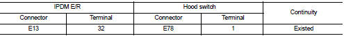
2. Check continuity between IPDM E/R harness connector and hood switch harness connector.
3. Check continuity between IPDM E/R harness connector and ground.
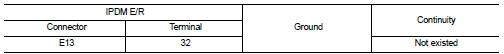
Is the inspection result normal? YES >> Replace IPDM E/R. Refer to PCS-63, "Removal and Installation".
NO >> Repair or replace harness.
3.CHECK HOOD SWITCH GROUND CIRCUIT
Check continuity between hood switch harness connector and ground.
Is the inspection result normal? YES >> GO TO 4.
NO >> Repair or replace harness.
4.CHECK HOOD SWITCH
Refer to SEC-224, "Component Inspection".
Is the inspection result normal? YES >> GO TO 5.
NO >> Replace hood switch.
5.CHECK INTERMITTENT INCIDENT
Refer to GI-42, "Intermittent Incident".
>> INSPECTION END
Component Inspection
1.CHECK HOOD SWITCH
1. Turn ignition switch OFF.
2. Disconnect hood switch connector.
3. Check continuity between hood switch terminals.
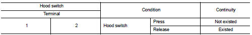
Is the inspection result normal? YES >> INSPECTION END
NO >> Replace hood switch.
 B210E starter relay
DTC Logic
DTC DETECTION LOGIC
NOTE:
• If DTC B210E is displayed with DTC U1000, first perform the trouble diagnosis
for DTC U1000. Refer to
PCS-59, "DTC Logic".
• If DTC B210E is disp ...
 Horn function
Component Function Check
1.CHECK FUNCTION 1
1. Disconnect vehicle security horn relay.
2. Perform “VEHICLE SECURITY HORN” in “ACTIVE TEST” mode of “THEFT ALM” of “BCM”
using CONSULT-
III.
3. Ch ...
Other materials:
Additional service when replacing control unit
ECM
ECM : Description
Performing the following procedure can automatically activate recommunication
of ECM and BCM, but only
when the ECM is replaced with a new one*.
*: New one means a virgin ECM that has never been energized on-board.
(In this step, initialization procedure by CONSULT-I ...
For frontal collision : When SRS is not activated in a collision
CAUTION:
Due to varying models and option levels, not all parts listed in the chart below
apply to all vehicles.
WORK PROCEDURE
1. Before performing any of the following steps, ensure that all vehicle body
and structural repairs have been
completed.
2. Check the SRS components using the t ...
Vehicle speed sensing auto lock operation does not operate
Diagnosis Procedure
1.CHECK “AUTOMATIC LOCK/UNLOCK SELECT” SETTING IN “WORK SUPPORT”
1. Select “DOOR LOCK” of “BCM” using CONSULT-III.
2. Select “AUTOMATIC LOCK/UNLOCK SELECT” in “WORK SUPPORT” mode.
3. Check “AUTOMATIC LOCK/UNLOCK SELECT” setting in “WORK SUPPORT”.
Refer to DLK-501, "DO ...
