Nissan Juke Service and Repair Manual : Hood switch
Component Function Check
1.CHECK FUNCTION
1. Select “HOOD SW” in “Data Monitor” mode of “IPDM E/R” using CONSULT-III.
2. Check “HOOD SW” indication under the following condition.
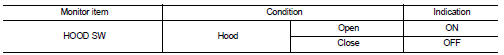
Is the indication normal? YES >> Hood switch is OK.
NO >> Go to SEC-155, "Diagnosis Procedure".
Diagnosis Procedure
1.CHECK HOOD SWITCH SIGNAL CIRCUIT 1
1. Turn ignition switch OFF.
2. Disconnect hood switch connector.
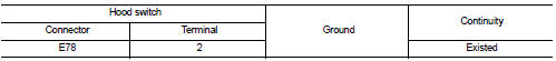
3. Check voltage between hood switch harness connector and ground.
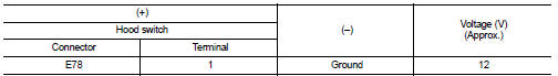
Is the inspection result normal? YES >> GO TO 3.
NO >> GO TO 2.
2.CHECK HOOD SWITCH SIGNAL CIRCUIT 2
1. Disconnect IPDM E/R connector.
2. Check continuity between IPDM E/R harness connector and hood switch harness connector
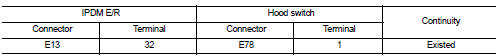
3. Check continuity between IPDM E/R harness connector and ground.
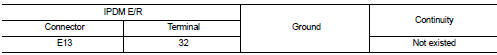
Is the inspection result normal? YES >> Replace IPDM E/R. Refer to PCS-34, "Removal and Installation".
NO >> Repair or replace harness.
3.CHECK HOOD SWITCH GROUND CIRCUIT
Check continuity between hood switch harness connector and ground.
Is the inspection result normal? YES >> GO TO 4.
NO >> Repair or replace harness.
4.CHECK HOOD SWITCH
Refer to SEC-156, "Component Inspection".
Is the inspection result normal? YES >> GO TO 5.
NO >> Replace hood switch.
5.CHECK INTERMITTENT INCIDENT
Refer to GI-42, "Intermittent Incident".
>> INSPECTION END
Component Inspection
1.CHECK HOOD SWITCH
1. Turn ignition switch OFF.
2. Disconnect hood switch connector.
3. Check continuity between hood switch terminals
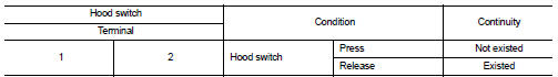
Is the inspection result normal? YES >> INSPECTION END
NO >> Replace hood switch.
 B2110 shift position/clutch interlock switch
DTC Logic
DTC DETECTION LOGIC
NOTE:
If DTC B2110 is displayed with DTC U1000, first perform the trouble diagnosis
for DTC U1000. Refer to PCS-
30, "DTC Logic".
DTC CONFIRMATION PROC ...
 Horn function
Component Function Check
1.CHECK FUNCTION 1
1. Disconnect vehicle security horn relay.
2. Perform “VEHICLE SECURITY HORN” in “ACTIVE TEST” mode of “THEFT ALM” of “BCM”
using CONSULT-
III.
3. ...
Other materials:
P1212 TCS communication line
Description
This CAN communication line is used to control the smooth engine operation
during the TCS operation. Pulse
signals are exchanged between ECM and “ABS actuator and electric unit (control
unit)”.
Be sure to erase the malfunction information such as DTC not only for “ABS
actuator ...
Door lock status indicator does not illuminate
Diagnosis Procedure
1.CHECK DOOR LOCK STATUS INDICATOR
Check door lock status indicator.
Refer to DLK-83, "Component Function Check".
Is the inspection result normal?
YES >> GO TO 2.
NO >> Repair or replace the malfunctioning parts.
2.REPLACE BCM
1. Replace BCM. ...
C1606 EPS motor
DTC Logic
DTC DETECTION LOGIC
DTC CONFIRMATION PROCEDURE
1.PRECONDITIONING
If “DTC CONFIRMATION PROCEDURE” has been previously conducted, always turn
ignition switch OFF and
wait at least 10 seconds before conducting the next test.
>> GO TO 2.
2.DTC REPRODUCTION PROCEDURE
With ...
