Nissan Juke Service and Repair Manual : Hood lock
Exploded View
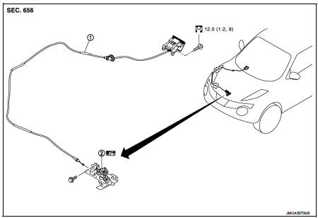
1. Hood lock control cable assembly 2. Hood lock assembly
 : Clip
 : N·m (kg-m, ft-lb)
 : Body grease
Hood lock
HOOD LOCK : Removal and Installation
REMOVAL
1. Remove front center grille. Refer to EXT-18, "Removal and Installation".
2. Remove crash zone sensor. Refer to SR-26, "Removal and Installation".
3. Remove hood lock assembly mounting bolts, and then remove hood lock assembly.
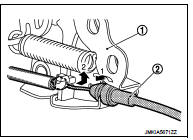
4. Disconnect hood lock control cable assembly (2) from hood lock assembly (1).
INSTALLATION
Note the following items, and install in the reverse order of removal.
CAUTION: • Check that hood lock control cable is properly engaged with hood lock.
• After installation, perform hood fitting adjustment. Refer to DLK-440, "HOOD ASSEMBLY : Adjustment".
• After installation, perform hood lock control inspection. Refer to DLK-471, "Inspection".
Hood lock control cable
HOOD LOCK CONTROL CABLE : Removal and Installation
REMOVAL
1. Disconnect hood lock control cable assembly from hood lock assembly.
2. Remove fender protector (RH). Refer to EXT-22, "Removal and Installation".
3. Remove hood lock cable clip.
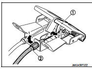
4. Remove hood lock control cable assembly of instrument lower panel (RH), and then remove fuel filler lid opener cable (2) from fuel filler lid opener lever (1).
5. Remove grommet on the lower dash, and pull the hood lock control cable toward the passenger compartment.
CAUTION:
While pulling, never to damage (peeling) the outside of hood lock control cable.
INSTALLATION
Note the following items, and install in the reverse order of removal.
CAUTION:
• Never to bend cable too much, keeping the radius 100 mm (3.937 in) or more.
• Check that cable is not offset from the positioning grommet, and apply the sealant to the grommet (at * mark) properly.
• Check that hood lock control cable is properly engaged with hood lock.
• After installation, perform hood fitting adjustment. Refer to DLK-440, "HOOD ASSEMBLY : Adjustment".
• After installation, perform hood lock control inspection. Refer to DLK-471, "Inspection".
Inspection
NOTE
:
If the hood lock cable is bent or deformed, replace it.
1. Check that secondary latch is securely engaged with securely striker from the dead load of the hood assembly.
2. Check that primary latch is securely engaged with primary striker when hood assembly is closed [free-fall from approximately 200 mm (7.874 in) height].
CAUTION:
Never free-fall hood assembly from a height of 300 (11.811 in) mm or more.
3. While operating the hood opener carefully, check that the front end of the hood is lifted by approximately 20 mm (0.787 in) (A). Also, check that the hood opener returns to the original position.
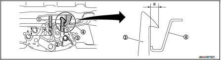
1. Primary striker
2. Primary latch
3. Secondary latch
4. Secondary striker
4. Check that secondary latch is properly engaged with secondary striker [6.8 mm (0.268 in)] (B).
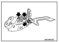
5. Check the hood lock lubrication condition. If necessary, apply body grease to hood lock.
 : Grease up point
 Back door
Exploded View
REMOVAL
1. Back door weather-strip
2. Back door stay
3. Back door stay lower bracket
4. Bumper rubber
5. Back door striker
6. Back door panel
7. Back door hinge
8. Hole c ...
 Front door lock
Exploded View
1. Door key cylinder assembly (driver
side)
Outside handle escutcheon (passenger
side)
2. Outside handle
3. Front gasket
4. Inside handle
5. TORX bolt
6. Door lock assembly ...
Other materials:
C1121, C1123, C1125, C1127 ABS out valve system
DTC Logic
DTC DETECTION LOGIC
DTC CONFIRMATION PROCEDURE
1.PRECONDITIONING
If “DTC CONFIRMATION PROCEDURE” has been previously conducted, always turn
ignition switch OFF and
wait at least 10 seconds before conducting the next test.
>> GO TO 2.
2.CHECK DTC DETECTION
With CONSULT ...
Diagnosis and repair workflow
Work Flow
INTRODUCTION
The TCM receives a signal from the vehicle speed sensor, transmission range
switch and provides shift control
or lock-up control via CVT solenoid valves.
The TCM also communicates with the ECM by means of a signal
sent from sensing elements used with the OBD-related p ...
Brake fluid level switch
Component Function Check
1.CHECK BRAKE FLUID LEVEL SWITCH OPERATION
When the brake fluid is full or empty. Then check that the brake warning lamp
in the combination meter turns
ON/OFF correctly.
Is the inspection result normal?
YES >> INSPECTION END
NO >> Proceed to BRC-72, &qu ...
