Nissan Juke Service and Repair Manual : High pressure fuel pump
Component Function Check
1.CHECK HIGH PRESSURE FUEL PUMP FUNCTION
 With CONSULT-III
1. Start engine.
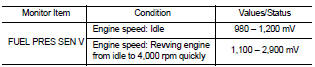
2. Check “FUEL PRES SEN V” in “DATA MONITOR” mode of “ENGINE” using CONSULT-III.
 Without CONSULT-III
1. Start engine.
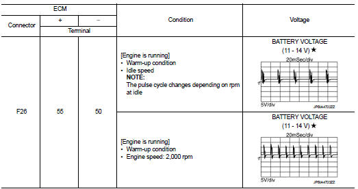
2. Check the voltage between ECM harness connector terminals as per the following conditions.
Is the inspection result normal? YES >> INSPECTION END
NO >> Proceed to EC-410, "Diagnosis Procedure".
Diagnosis Procedure
1.CHECK HIGH PRESSURE FUEL PUMP POWER SUPPLY
1. Turn ignition switch ON.
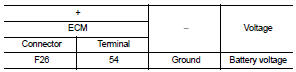
2. Check the voltage between ECM harness connector and ground.
Is inspection result normal?
YES >> GO TO 8.
NO >> GO TO 2.
2.CHECK HIGH PRESSURE FUEL PUMP POWER SUPPLY CIRCUIT
1. Turn ignition switch OFF.
2. Disconnect ECM harness connector.
3. Disconnect fuel injector relay harness connector.
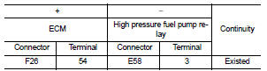
4. Check the continuity between ECM harness connector and high pressure fuel pump relay harness connector.
5. Also check harness for short to ground.
Is the inspection result normal? YES >> GO TO 3.
NO >> Repair or replace error-detected parts
3.CHECK HIGH PRESSURE FUEL PUMP RELAY POWER SUPPLY (CONTACT SIDE)
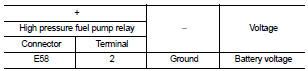
Check the voltage between high pressure fuel pump relay harness connector and ground.
Is the inspection result normal? YES >> GO TO 4.
NO >> Perform the trouble diagnosis for power supply circuit.
4.CHECK HIGH PRESSURE FUEL PUMP RELAY POWER SUPPLY (EXCITATION COIL SIDE)
1. Reconnect all harness connectors disconnected.
2. Turn ignition switch ON.
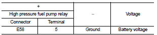
3. Check the voltage between high pressure fuel pump relay harness connector and ground.
Is the inspection result normal? YES >> GO TO 6.
NO >> GO TO 5 5.CHECK HIGH PRESSURE FUEL PUMP RELAY POWER SUPPLY CIRCUIT (EXCITATION COIL SIDE)
1. Turn ignition switch OFF.
2. Disconnect high pressure fuel pump relay harness connector.
3. Disconnect IPDM E/R harness connector.
4. check the continuity between ipdm e/r harness connector and high pressure fuel pump harness connector.
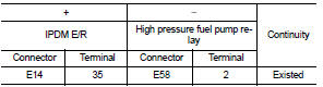
5. Also check harness for short to ground.
Is the inspection result normal? YES >> Perform the trouble diagnosis for power supply circuit.
NO >> Repair or replace error-detected parts.
6.CHECK HIGH PRESSURE FUEL PUMP RELAY GROUND CIRCUIT
1. Turn ignition switch OFF.
2. Disconnect high pressure fuel pump relay harness connector.
3. Check the continuity between high pressure fuel pump relay harness connector and ground.
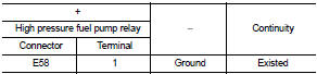
4. Also check harness for short to power.
Is the inspection result normal? YES >> GO TO 7.
NO >> Repair or replace error-detected parts.
7.CHECK HIGH PRESSURE FUEL PUMP RELAY
Check the high pressure fuel pump relay. Refer to EC-413, "Component Inspection (High Pressure Fuel Pump Relay)".
Is inspection result normal? YES >> GO TO 8.
NO >> Replace high pressure fuel pump relay. Refer to PG-7, "Standardized Relay".
8.CHECK HIGH PRESSURE FUEL PUMP CIRCUIT
1. Turn ignition switch OFF.
2. Disconnect ECM harness connector and high pressure fuel pump harness connector.
3. Check the continuity between ECM harness connector and high pressure fuel pump harness connector.
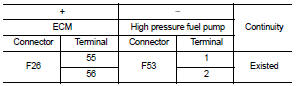
4. Also check harness for short to ground and to power.
Is inspection result normal? YES >> GO TO 9.
NO >> Repair or replace error-detected parts.
9.CHECK HIGH PRESSURE FUEL PUMP
Check the high pressure fuel pump. Refer to EC-413, "Component Inspection".
Is inspection result normal? YES >> GO TO 10.
NO >> Replace high pressure fuel pump. Refer to EM-43, "Exploded View".
10.CHECK HIGH PRESSURE FUEL PUMP INSTALLATION CONDITION
1. Turn ignition switch OFF.
2. Check that the high pressure fuel pump is installed with no backlash and looseness.
Is the inspection result normal? YES >> GO TO 11.
NO >> Repair or replace error-detected parts.
11.CHECK CAMSHAFT
1. Remove camshaft. Refer to EM-78, "Exploded View".
2. Check camshaft. Refer to EM-82, "Inspection".
Is inspection result normal? YES >> Check intermittent incident. Refer to GI-42, "Intermittent Incident".
NO >> Replace camshaft. Refer to EM-78, "Exploded View".
Component Inspection
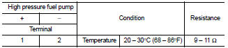
1.CHECK HIGH PRESSURE FUEL PUMP SOLENOID
1. Turn ignition switch OFF.
2. Disconnect high pressure fuel pump harness connector.
3. Check the resistance between high pressure fuel pump connector terminals as per the following.
Is the inspection result normal? YES >> INSPECTION END
NO >> Replace high pressure fuel pump. Refer to EM-43, "Exploded View".
Component Inspection (High Pressure Fuel Pump Relay)
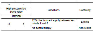
1.CHECK HIGH PRESSURE FUEL PUMP RELAY
1. Turn ignition switch OFF.
2. Remove high pressure fuel pump relay. Refer to PG-7, "Standardized Relay".
3. Check the continuity between high pressure fuel pump relay terminals as per the following conditions.
Is the inspection result normal? YES >> INSPECTION END
NO >> Replace high pressure fuel pump relay. Refer to PG-7, "Standardized Relay".
 Low pressure fuel pump
M/T models : Component Function Check
1.CHECK FUEL PUMP FUNCTION
1. Turn ignition switch ON.
2. Pinch fuel feed hose with two fingers.
NOTE:
Fuel pressure pulsation should be felt on the fuel f ...
 Ignition signal
Component Function Check
1.INSPECTION START
Turn ignition switch OFF, and restart engine.
Does the engine start?
YES >> GO TO 2.
NO >> Proceed to EC-414, "Diagnosis Procedure ...
Other materials:
Cooling fan
Component Function Check
1.CHECK COOLING FAN FUNCTION
With CONSULT-III
1. Turn ignition switch ON.
2. Perform “FAN DUTY CONTROL” in “ACTIVE TEST” mode of “ENGINE” using
CONSULT-III.
3. Check that cooling fan speed varies according to the percentage.
Without CONSULT-III
1. Activate IPDM E/ ...
4WD warning lamp
Component Function Check
1.CHECK 4WD WARNING LAMP FUNCTION
1. Turn the ignition switch ON.
2. Check that 4WD warning lamp turns on.
Is the inspection result normal?
YES >> INSPECTION END
NO >> Proceed to diagnosis procedure. Refer to DLN-80, "Diagnosis Procedure".
Diag ...
Steering switch signal B circuit
Description
Transmits the steering switch signal to audio unit.
Diagnosis Procedure
1.CHECK STEERING SWITCH SIGNAL B CIRCUIT
1. Disconnect audio unit connector and spiral cable connector.
2. Check continuity between audio unit harness connector and spiral cable
harness connector.
3. Check ...
