Nissan Juke Service and Repair Manual : Heater control
Exploded View
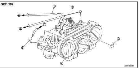
1. Intake door cable
2. Air mix door cable
3. Mode door cable
4. Heater control
5. Intake door lever knob
A. To intake door link B. To air mix door link C. To mode door link
Removal and Installation
REMOVAL
1. Remove A/C finisher. Refer to IP-13, "Removal and Installation".
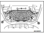
2. Remove heater control fixing screws (A) and fixing pawls, and then remove heater control.
 : Pawl
3. Disconnect door cable and harness connector from heater control.
INSTALLATION
Install in the reverse order of removal.

 Blower fan resistor
Exploded View
1. Heater unit assembly
2. Fan control amp.*1
3. Blower fan resistor*2
4. Blower motor
5. Blower motor cover
• *1: Automatic air conditioner
• *2: Manual air conditioner or M ...
Other materials:
Evaporative emission system
Evaporative emission system: System
Diagram
Evaporative emission system : System
Description
INPUT/OUTPUT SIGNAL CHART
*: ECM determines the start signal status by the signals of engine speed and
battery voltage.
SYSTEM DESCRIPTION
The evaporative emission system is used to reduce hy ...
Wiring diagram
AUDIO WITH NAVIGATION
Wiring Diagram
For connector terminal arrangements, harness layouts, and alphabets in a
(option abbreviation; if not
described in wiring diagram), refer to GI-12, "Connector Information/Explanation
of Option Abbreviation".
...
Diagnosis system (ECM)
Diagnosis description
Diagnosis description : 1st Trip Detection
Logic and Two Trip Detection Logic
When a malfunction is detected for the first time, 1st trip DTC and 1st trip
Freeze Frame data are stored in the
ECM memory. The MIL will not illuminate at this stage. <1st trip>
If the s ...
