Nissan Juke Service and Repair Manual : Headlamp aiming adjustment
LHD
LHD : Description
PREPARATION BEFORE ADJUSTING
NOTE
:
• For details, refer to the regulations in your own country.
• Perform aiming if the vehicle front body has been repaired and/or the headlamp assembly has been replaced.
Before performing aiming adjustment, check the following.
• Adjust the tire pressure to the specification.
• Fill with fuel, engine coolant and each oil.
• Maintain the unloaded vehicle condition. (Remove luggage from the passenger compartment and the luggage room.) NOTE
:
Do not remove the temporary tire, jack and on-vehicle tool.
• Wipe out dirt on the headlamp.
CAUTION:
Never use organic solvent (thinner, gasoline etc.)
• Ride alone on the driver seat.
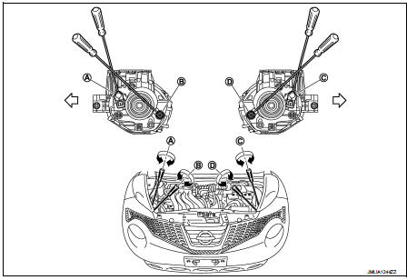
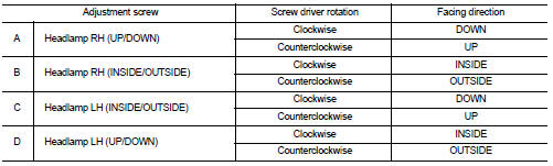
AIMING ADJUSTMENT SCREW
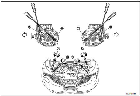
A. Headlamp RH (INSIDE/OUTSIDE)
adjustment screw
B. Headlamp RH (UP/DOWN)
adjustment screw
C. Headlamp LH (INSIDE/OUTSIDE)
adjustment screw
D. Headlamp LH (UP/DOWN)
adjustment screw
 : Vehicle center
LHD : Aiming Adjustment Procedure
1. Place the screen.
NOTE
:
• Stop the vehicle at the perpendicular angle to the wall.
• Set the screen so that it is perpendicular to a level load surface.
2. Face the vehicle squarely toward the screen and make the distance between the headlamp center and the screen 10 m (32.8 ft).
3. Start the engine and illuminate the headlamp (LO).
NOTE
:
Block light from the headlamp that is not being adjusted with a thick fabric or
another object, so that it
does not reach the adjustment screen.
CAUTION:
Do not cover lens surface with tape, etc. because it is made from plastic.
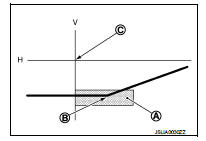
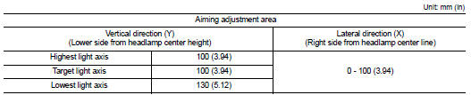
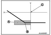
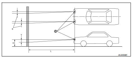
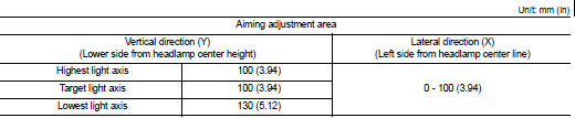
4. Use the aiming adjustment screw to adjust the elbow point projected by the low beams on the screen, so that it is within the aiming adjustment area.
Low beam distribution on the screen
A. Aiming adjustment area
B. Elbow point
C. Headlamp center
H. Horizontal center line of headlamp
V. Vertical center line of headlamp
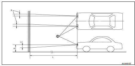
C. Vertical center line of headlamp
H. Horizontal center line of headlamp
L. Distance from headlamp center to screen
X. Aiming adjustment area
(lateral)
Y. Aiming adjustment area
(Vertical)
Distance from headlamp center to screen (L) : 10 m (32.8 ft)
RHD
RHD : Description
PREPARATION BEFORE ADJUSTING
NOTE
:
• For details, refer to the regulations in your own country.
• Perform aiming if the vehicle front body has been repaired and/or the headlamp assembly has been replaced.
Before performing aiming adjustment, check the following.
• Adjust the tire pressure to the specification.
• Fill with fuel, engine coolant and each oil.
• Maintain the unloaded vehicle condition. (Remove luggage from the passenger compartment and the luggage room.) NOTE
:
Do not remove the temporary tire, jack and on-vehicle tool.
• Wipe out dirt on the headlamp.
CAUTION:
Never use organic solvent (thinner, gasoline etc.)
• Ride alone on the driver seat.
AIMING ADJUSTMENT SCREW
A. Headlamp RH (INSIDE/OUTSIDE)
adjustment screw
B. Headlamp RH (UP/DOWN)
adjustment screw
C. Headlamp LH (INSIDE/OUTSIDE)
adjustment screw
D. Headlamp LH (UP/DOWN)
adjustment screw
 : Vehicle center
RHD : Aiming Adjustment Procedure
1. Place the screen.
NOTE
:
• Stop the vehicle at the perpendicular angle to the wall.
• Set the screen so that it is perpendicular to a level load surface.
2. Face the vehicle squarely toward the screen and make the distance between the headlamp center and the screen 10 m (32.8 ft).
3. Start the engine and illuminate the headlamp (LO).
NOTE
:
Block light from the headlamp that is not being adjusted with a thick fabric or
another object, so that it
does not reach the adjustment screen.
CAUTION
:
Do not cover lens surface with tape, etc. because it is made from plastic.
4. Use the aiming adjustment screw to adjust the elbow point projected by the low beams on the screen, so that it is within the aiming adjustment area.
Low beam distribution on the screen
A. Aiming adjustment area
B. Elbow point
C. Headlamp center
H. Horizontal center line of headlamp
V. Vertical center line of headlamp
C. Vertical center line of headlamp
H. Horizontal center line of headlamp
L. Distance from headlamp center to screen
X. Aiming adjustment area
(lateral)
Y. Aiming adjustment area
(Vertical)
Distance from headlamp center to screen (L) : 10 m (32.8 ft)

 Front fog lamp aiming adjustment
Description
PREPARATION BEFORE ADJUSTING
NOTE:
For details, refer to the regulations in your own country.
Before performing aiming adjustment, check the following.
• Adjust the tire pressure ...
Other materials:
General Precauti
• Always use a 12 volt battery as power source.
• Do not attempt to disconnect battery cables while engine is
running.
• Before connecting or disconnecting the ECM harness connector,
turn ignition switch OFF and disconnect negative battery
cable. Failure to do so may damage the ECM because
bat ...
P0524 engine oil pressure
DTC Logic
DTC DETECTION LOGIC
NOTE:
If DTC P0524 is displayed with DTC P0520, P0075, or P0081, perform trouble
diagnosis for DTC P0520,
P0075, or P0081 first. Refer to EC-176, "DTC Logic".
DTC CONFIRMATION PROCEDURE
1.PRECONDITIONING
If DTC Confirmation Procedure has been previo ...
P012B TC boost sensor
DTC Logic
DTC DETECTION LOGIC
Diagnosis Procedure
1.CHECK GROUND CONNECTIONS
1. Turn ignition switch OFF.
2. Check ground connection E38. Refer to Ground inspection in GI-44, "Circuit
Inspection".
Is the inspection result normal?
YES >> GO TO 2.
NO >> Repair or ...
