Nissan Juke Service and Repair Manual : Headlamp
Exploded View
REMOVAL
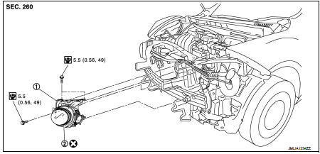
1. Headlamp assembly 2. EPT sealer [2.8 mm (0.110 in)]
 : Do not reuse
 : N·m (kg-m, in-lb)
DISASSEMBLY
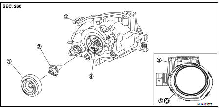
1. Back cover 2. Halogen bulb 3. Headlamp housing assembly 4. Retaining spring 5. EPT sealer [2.8 mm (0.110 in)]
 : Do not reuse
Removal and Installation
CAUTION:
Disconnect the battery negative terminal or the fuse.
REMOVAL
1. Remove front bumper fascia. Refer to EXT-13, "Removal and Installation".
2. Remove headlamp mounting bolts.
3. Pull out the headlamp assembly forward the vehicle, and then disconnect the connector before removing the headlamp assembly.
INSTALLATION
Note the following item, and then install in the reverse order of removal.
CAUTION:
After installation, perform aiming adjustment. Refer toEXL-83, "LHD :
Description".
Replacement
CAUTION:
• Disconnect the battery negative terminal or remove the fuse.
• After installing the bulb, install the resin cap and the bulb socket securely for watertightness.
• Never touch the glass of bulb directly by hand. Keep grease and other oily matters away from it.
• Never touch bulb by hand while it is lit or right after being turned off.
• Never leave bulb out of lamp reflector for a long time because dust, moisture smoke, etc. may affect the performance of lamp. When replacing bulb, be sure to replace it with new one.
HEADLAMP BULB
1. Disconnect headlamp bulb connector.
2. Remove back cover.
3. Remove retaining spring lock, and then remove bulb from the headlamp housing assembly.
Disassembly and Assembly
DISASSEMBLY
1. Remove back cover.
2. Remove retaining spring lock, and then remove bulb from the headlamp housing assembly.
ASSEMBLY
Note the following item, and then assemble in the reverse order of disassembly.
CAUTION:
After installing the bulb, install the resin cap and the bulb socket securely
for watertightness.

 Front combination lamp
Exploded View
REMOVAL
1. Front combination lamp
: N·m (kg-m, in-lb)
DISASSEMBLY
1. Parking lamp bulb
2. Parking lamp bulb socket
3. Front turn signal lamp bulb socket
4. Front turn signa ...
Other materials:
Push-button ignition switch illumination circuit
Description
Provides the power supply and the ground to control the push-button ignition
switch illumination.
Component Function Check
1.CHECK PUSH-BUTTON IGNITION SWITCH ILLUMINATION OPERATION
CONSULT-III ACTIVE TEST
1. Turn the ignition switch ON.
2. Select “ENGINE SW ILLUMI” of BCM (INTEL ...
U1000 can comm circuit
Description
CAN (Controller Area Network) is a serial communication line for real time
application. It is an on-vehicle multiplex
communication line with high data communication speed and excellent error
detection ability. Many electronic
control units are equipped onto a vehicle, and each co ...
Precaution for Supplemental Restraint System (SRS) "AIR BAG" and "SEAT BELT
PRE-TENSIONER"
The Supplemental Restraint System such as “AIR BAG” and “SEAT BELT PRE-TENSIONER”,
used along
with a front seat belt, helps to reduce the risk or severity of injury to the
driver and front passenger for certain
types of collision. Information necessary to service the system safely is
include ...
