Nissan Juke Service and Repair Manual : Hazard switch
Component Function Check
1.CHECK HAZARD SWITCH SIGNAL BY CONSULT-III
 CONSULT-III DATA MONITOR
1. Turn the ignition switch ON.
2. Select “HAZARD SW” of BCM (FLASHER) data monitor item.
3. With operating the hazard switch, check the monitor status.
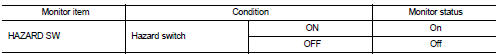
Is the inspection result normal? YES >> Hazard switch circuit is normal.
NO >> Refer to EXL-72, "Diagnosis Procedure".
Diagnosis Procedure
1.CHECK HAZARD SWITCH SIGNAL INPUT
1. Turn ignition switch OFF.
2. Disconnect hazard switch connector.
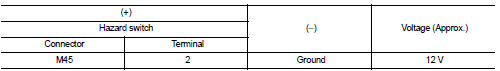
3. Check voltage between hazard switch connector and ground.
Is the inspection result normal? YES >> GO TO 4.
NO >> GO TO 2.
2.CHECK HAZARD SWITCH SIGNAL OPEN CIRCUIT
1. Disconnect BCM connector.
2. Check continuity between hazard switch harness connector and BCM harness connector.
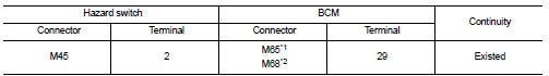
*1: Without Intelligent Key *2: With Intelligent Key
Is the inspection result normal? YES >> GO TO 3.
NO >> Repair or replace harness.
3.CHECK HAZARD SWITCH SIGNAL SHORT CIRCUIT
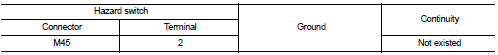
Check continuity between hazard switch harness connector and ground.
Is the inspection result normal?
YES >> Replace BCM. Refer to BCS-93, "Removal and Installation" (with Intelligent Key) or BCS-161, "Removal and Installation" (without Intelligent Key).
NO >> Repair or replace harness.
4.CHECK HAZARD SWITCH GROUND OPEN CIRCUIT
Check continuity between hazard switch harness connector and ground.
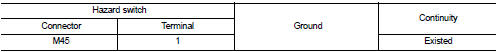
Is the inspection result normal? YES >> Replace hazard switch.
NO >> Repair or replace harness.
 Turn signal lamp circuit
Component Function Check
1.CHECK TURN SIGNAL LAMP
CONSULT-III ACTIVE TEST
1. Select “FLASHER” of BCM (FLASHER) active test item.
2. With operating the test items, check that the turn signal lamps ...

Other materials:
Front door
Exploded View
1. Front door panel
2. Grommet
3. TORX bolt
4. Door striker
5. Door pad
6. Bumper rubber
7. Door check link
8. Door hinge (lower)
9. Door hinge (upper)
10. Grommet
: Do not reuse
: N·m (kg-m, in-lb)
: N·m (kg-m, ft-lb)
: Body grease
Door assembly
DOOR ASSEMBLY : ...
System
System Description
• The system switches fluid pressure of each brake caliper to increase, to
hold or to decrease according to
signals from control unit in ABS actuator and electric unit (control unit). This
control system is applied to ESP
function, TCS function, ABS function, EBD function a ...
P0327, P0328 KS
DTC Logic
DTC DETECTION LOGIC
DTC CONFIRMATION PROCEDURE
1.PRECONDITIONING
If DTC Confirmation Procedure has been previously conducted, always perform
the following procedure
before conducting the next test.
1. Turn ignition switch OFF and wait at least 10 seconds.
2. Turn ignition swit ...
