Nissan Juke Service and Repair Manual : Fuel pressure control
Fuel pressure control : System Diagram
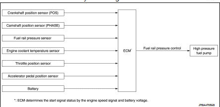
Fuel pressure controlL : System Description
INPUT/OUTPUT SIGNAL CHART
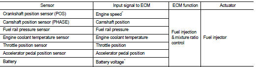
*: ECM determines the start signal status by the engine speed signal and battery voltage.
CVT models
System Description
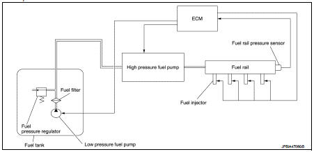
Low fuel pressure control • The low fuel pressure pump is controlled by ECM. The pumped fuel passes through the fuel filter and is sent to the high pressure fuel pump.
• Low fuel pressure is adjusted by the fuel pressure regulator.
High fuel pressure control The high pressure fuel pump raises the pressure of the fuel sent from the low pressure fuel pump. Actuated by the camshaft, the high pressure fuel pump activates the high pressure fuel pump solenoid based on a signal received from ECM, and adjusts the amount of discharge by changing the timing of closing the inlet check valve to control fuel rail pressure.
M/T models
System Description
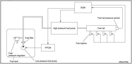
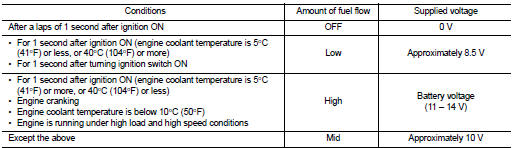
Low fuel pressure control • The low fuel pressure pump is controlled by the fuel pump control module (FPCM) and pumps fuel according to a driving condition. The pumped fuel passes through the fuel filter and is sent to the high pressure fuel pump. FPCM controls the low pressure fuel pump, according to a signal from ECM as shown in the table below.
• Low fuel pressure is adjusted by the fuel pressure regulator.
High fuel pressure control The high pressure fuel pump raises the pressure of the fuel sent from the low pressure fuel pump. Actuated by the camshaft, the high pressure fuel pump activates the high pressure fuel pump solenoid based on a signal received from ECM, and adjusts the amount of discharge by changing the timing of closing the inlet check valve to control fuel rail pressure
 Direct injection gasoline system
Direct injection gasoline system : System Diagram
Direct injection gasoline system : System Description
INPUT/OUTPUT SIGNAL CHART
*1: This sensor is not used to control the engine system under ...
 Electric ignition system
Electric ignition system : System Diagram
Electric ignition system : System Description
INPUT/OUTPUT SIGNAL CHART
*1: CVT models
*2: M/T models
*3: ECM determines the start signa ...
Other materials:
EPS warning lamp does not turn on
Description
EPS warning lamp does not turn ON when turning ignition switch ON from OFF.
(Check the illumination of the
EPS warning lamp.)
Diagnosis Procedure
1.CHECK EPS WARNING LAMP
Perform the trouble diagnosis of EPS warning lamp. Refer to STC-26,
"Diagnosis Procedure".
Is t ...
B2108 steering lock relay
DTC Logic
DTC DETECTION LOGIC
NOTE:
If DTC B2108 is displayed with DTC U1000, first perform the trouble diagnosis
for DTC U1000. Refer to PCS-
30, "DTC Logic".
DTC CONFIRMATION PROCEDURE
1.PERFORM DTC CONFIRMATION PROCEDURE
1. Press push-button ignition switch under the followin ...
Removal and Installation Procedure for CVT Unit Connector
REMOVAL
• Rotate bayonet ring (A) counterclockwise. Pull out CVT unit harness
connector (B) upward and remove it.
INSTALLATION
1. Align marking (A) on CVT unit harness connector terminal with
marking (B) on bayonet ring. Insert CVT unit harness connector.
2. Rotate bayonet ring clockwise.
...
