Nissan Juke Service and Repair Manual : Fuel injector
Component Function Check
1.INSPECTION START
Turn ignition switch to START.
Is any cylinder ignited? YES >> GO TO 2.
NO >> Proceed to EC-400, "Diagnosis Procedure".
2.CHECK FUEL INJECTOR FUNCTION
 With CONSULT-III
1. Start engine.
2. Perform “POWER BALANCE” in “ACTIVE TEST” mode of “ENGINE” using CONSULT-III.
3. Check that each circuit produces a momentary engine speed drop.
 Without CONSULT-III
1. Let engine idle.
2. Listen to each fuel injector operating sound.
Clicking noise should be heard.
Is the inspection result normal? YES >> INSPECTION END
NO >> Proceed to EC-400, "Diagnosis Procedure".
Diagnosis Procedure
1.CHECK FUEL INJECTOR POWER SUPPLY CIRCUIT
1. Turn ignition switch OFF.
2. Disconnect fuel injector harness connector.
3. Turn ignition switch ON.
4. Check the voltage between fuel injector harness connector and ground.
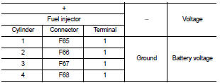
Is the inspection result normal? YES >> GO TO 9.
NO >> GO TO 2.
2.CHECK FUEL INJECTOR POWER SUPPLY CIRCUIT
1. Turn ignition switch OFF.
2. Disconnect ECM harness connector.
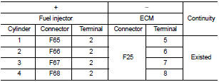
3. Check the continuity between fuel injector harness connector and ECM harness connector.
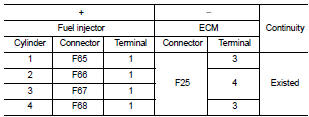
4. Also check harness for short to ground.
Is the inspection result normal? YES >> GO TO 3.
NO >> Repair or replace error-detected parts.
3.CHECK FUEL INJECTOR DRIVER POWER SUPPLY
1. Reconnect ECM harness connector.
2. Turn ignition switch ON.
3. Check the voltage between ECM harness connector and ground.
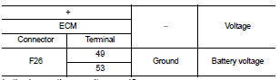
Is the inspection result normal? YES >> Check intermittent incident. Refer to GI-42, "Intermittent Incident" NO >> GO TO 4.
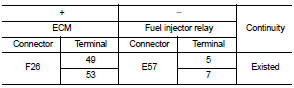
4.CHECK FUEL INJECTOR DRIVER POWER SUPPLY CIRCUIT
1. Turn ignition switch OFF.
2. Disconnect ECM harness connector.
3. Disconnect fuel injector relay harness connector.
4. Check the continuity between ECM harness connector and fuel injector relay harness connector.
5. Also check harness for short to ground.
Is the inspection result normal? YES >> GO TO 5.
NO >> Repair or replace error-detected parts 5.CHECK FUEL INJECTOR RELAY POWER SUPPLY (CONTACT SIDE)
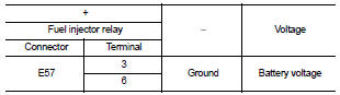
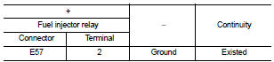
Check the voltage between fuel injector relay harness connector and ground.
Is the inspection result normal? YES >> GO TO 6.
NO >> Perform the trouble diagnosis for power supply circuit.
6.CHECK FUEL INJECTOR RELAY POWER SUPPLY (EXCITATION COIL SIDE)
1. Reconnect all harness connectors disconnected.
2. Turn ignition switch ON.
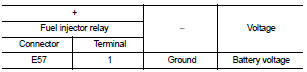
3. Check the voltage between fuel injector relay harness connector and ground.
Is the inspection result normal? YES >> GO TO 8.
NO >> GO TO 7.
7.CHECK FUEL INJECTOR RELAY POWER SUPPLY CIRCUIT (EXCITATION COIL SIDE)
1. Turn ignition switch OFF.
2. Disconnect fuel injector relay harness connector.
3. Disconnect IPDM E/R harness connector.
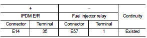
4. Check the continuity between IPDM E/R harness connector and fuel injector harness connector.
5. Also check harness for short to ground.
Is the inspection result normal? YES >> Perform the trouble diagnosis for power supply circuit.
NO >> Repair or replace error-detected parts.
8.CHECK FUEL INJECTOR RELAY GROUND CIRCUIT
1. Turn ignition switch OFF.
2. Disconnect fuel injector relay harness connector.
3. Check the continuity between fuel injector relay harness connector and ground.
4. Also check harness for short to power.
Is the inspection result normal? YES >> GO TO 10.
NO >> Repair or replace error-detected parts.
9.CHECK FUEL INJECTOR GROUND CIRCUIT
1. Turn ignition switch OFF.
2. Disconnect ECM harness connector.
3. Check the continuity between fuel injector harness connector and ECM harness connector.
4. Also check harness for short to ground and to power.
Is the inspection result normal? YES >> GO TO 11.
NO >> Repair or replace error-detected parts.
10.CHECK FUEL INJECTOR RELAY
Check the fuel injector relay. Refer to EC-403, "Component Inspection (Fuel Injector Relay)".
Is the inspection result normal? YES >> Check intermittent incident. Refer to GI-42, "Intermittent Incident" NO >> Replace fuel injector relay. Refer to PG-7, "Standardized Relay".
11.CHECK FUEL INJECTOR
Check the fuel injector. Refer to EC-403, "Component Inspection (Fuel Injector)".
Is the inspection result normal? YES >> Check intermittent incident. Refer to GI-42, "Intermittent Incident" NO >> Replace malfunctioning fuel injector. Refer to EM-47, "Exploded View".
Component Inspection (Fuel Injector)
1.CHECK FUEL INJECTOR
1. Turn ignition switch OFF.
2. Disconnect fuel injector harness connector.
3. Check resistance between fuel injector terminals as per the following.
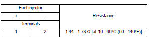
Is the inspection result normal? YES >> INSPECTION END
NO >> Replace malfunctioning fuel injector.EM-47, "Exploded View"
Component Inspection (Fuel Injector Relay)
1.CHECK FUEL INJECTOR RELAY
1. Turn ignition switch OFF.
2. Remove fuel injector relay. Refer to PG-7, "Standardized Relay".
3. Check the continuity between fuel heater relay terminals as per the following conditions.
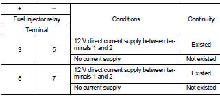
Is the inspection result normal? YES >> INSPECTION END
NO >> Replace fuel injector relay. Refer to PG-7, "Standardized Relay".
 P2162 vehicle speed sensor
Description
ECM receives a rear wheel sensor signal from ABS actuator and electric unit
(control unit) via CAN communication
to switch combustion for the direct injection gasoline system. For the ...
 Low pressure fuel pump
M/T models : Component Function Check
1.CHECK FUEL PUMP FUNCTION
1. Turn ignition switch ON.
2. Pinch fuel feed hose with two fingers.
NOTE:
Fuel pressure pulsation should be felt on the fuel f ...
Other materials:
Audio unit
Removal and Installation
REMOVAL
1. Remove cluster lid C. Refer to IP-12, "Exploded View".
2. Remove audio unit screws.
3. Disconnect audio unit connectors to remove audio unit and brackets as a
single unit.
4. Remove brackets screws to remove audio unit.
INSTALLATION
1. Install ...
Power supply and ground circuit
Navi control unit
NAVI CONTROL UNIT : Diagnosis Procedure
1.CHECK FUSE
Check for blown fuses.
Is inspection result OK?
YES >> GO TO 2.
NO >> Be sure to eliminate cause of malfunction before installing new fuse.
2.CHECK POWER SUPPLY CIRCUIT
Check voltage between NAVI control ...
Take away warning does not operate
Diagnosis Procedure
1.CHECK DTC WITH BCM AND COMBINATION METER
Check that DTC is not detected with BCM and combination meter.
Is the inspection result normal?
YES >> GO TO 2.
NO-1 >> Refer to BCS-67, "DTC Index". (BCM)
NO-2 >> Refer to MWI-36, "DTC Index&qu ...
