Nissan Juke Service and Repair Manual : Fuel filter
Exploded View
Removal and Installation
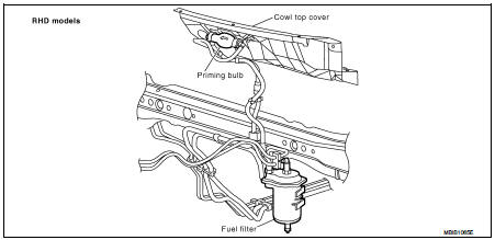
REMOVAL (RHD)
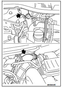
1. Remove quick connectors in the following procedures.
• Pinch quick connector square-parts with your fingers, and pull out the quick connector by hand.
• If quick connector and tube on vehicle are stuck, push and pull several times until they move, and pull out.
2. Remove fuel filter from fuel filter bracket.
CAUTION:
Never spill the fuel during removal. If the fuel is spill, immediately
wipe it off. Be especially careful to prevent the fuel
from adhering to the insulators of the engine mounts.

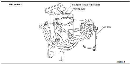
REMOVAL (LHD)
1. Remove priming bulb from priming bulb bracket.
2. Remove fuel filter from fuel filter bracket.
3. Remove quick connectors as above.
CAUTION:
Put a shop cloth under the drain valve, to avoid the water and fuel spill on ABS
actuator. Be especially
careful to prevent any damage.
INSTALLATION
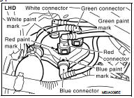
Install in the reverse order of removal, paying attention to the following points: • To install fuel filter connectors, respect paint marks on fuel filter as shown.
• After installation, operate the priming bulb vertically, if it is possible, to perform air bleeding.
Refer to FL-50, "Air Bleeding".
CAUTION:
Never bend or twist the tube during installation and removal.
Water Draining
DRAINING WATER (RHD)
CAUTION:
Before carrying out any work, wait for the fuel temperature is dropped.
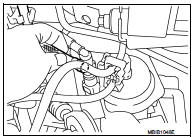
Open drain valve at the bottom of fuel filter.
DRAINING WATER (LHD)
1. Remove fender protector RH. Refer to EXT-22, "Exploded View".
2. Remove foam insulator.
3. Open drain valve at the bottom of fuel filter.
CAUTION:
Put a shop cloth under the drain valve, to avoid the water and fuel spill on ABS
actuator
.
FUEL FILTER CHECK
Check fuel filter for fuel leakage, damage and other abnormal signs.
Air Bleeding
1. Prime the circuit using the priming bulb.
2. Perform engine cranking with repeating several times until engine starting.
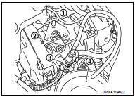
3. If the engine does not start, perform the following procedure.
2 : High pressure supply pump
a. Remove high pressure pump protector. Refer to EM-298, "Exploded View".
b. Remove quick connector (black tab).
c. Connect drain hose (suitable hose) (1) to the end of quick connector (supply pipe side) (3).
d. Place a tray (4) at the drain hose open end.
e. Operate the priming bulb to completely bleed air from the circuit.
4. When air bleeding is completed, install quick connector, and check absence of leakage.
 Fuel system
Checking Fuel Line
Inspect fuel lines and tank for improper attachment, leaks, cracks,
damage, chafing and deterioration.If necessary, repair or replace.
...

Other materials:
Auto retractable door mirror does not operate
Diagnosis Procedure
1.CHECK INTELLIGENT KEY AND DOOR REQUEST SWITCH OPERATION
Check operation of Intelligent Key and door request switch.
Is the inspection result normal?
YES >> GO TO 2.
NO >> Repair or replace the malfunctioning parts.
2.CHECK DOOR MIRROR (OPEN/CLOSE MOTOR) ...
Back door opener system
System Diagram
System Descr
BACK DOOR OPENER OPERATION
When back door opener switch is pressed, BCM operates back door opener
actuator.
NOTE:
Back door opener actuator is not for locking the back door. The function is only
to open the back door.
OPERATION CONDITION
If the following ...
Diagnosis system (BCM) (with intelligent key system)
Description
Air conditioning system performs self-diagnosis, operation check, function
diagnosis, and various settings
using diagnosis function of each control unit.
Common item : consult-III Function (BCM - COMMON ITEM)
APPLICATION ITEM
CONSULT-III performs the following functions via CAN ...
