Nissan Juke Service and Repair Manual : Front washer nozzle and tube
Exploded View
LHD models
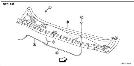
1. Front washer nozzle LH
2. Front washer nozzle RH
3. Cowl top cover
4. Front washer tube (tank side)
5. Front washer tube RH
6. Front washer tube LH
 : Vehicle front
Hydraulic Layout
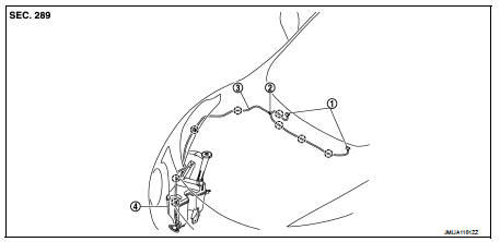
1. Front washer nozzle
2. Check valve
3. Front washer
4. Washer tank
 : Cli
: Cli
Removal and Installation
REMOVAL
1. Remove cowl top cover. Refer to EXT-20, "Removal and Installation".
2. Disconnect front washer tube from front washer nozzle.
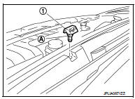
3. While pressing pawl (A) on the cowl top cover front side of front washer nozzle (1), remove front washer nozzle from cowl top cover.
INSTALLATION
Note the following item, and then install in the reverse order of removal.
CAUTION:
The spray positions differ, check that left and right nozzles are installed
correctly.
Inspection and Adjustment
INSPECTION
Check valve Inspection Check that air can pass through the hose by blowing forward (toward the nozzle (1)), and check that air cannot pass through by sucking.
ADJUSTMENT
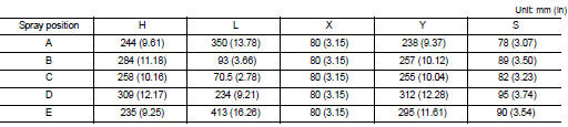
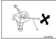
Washer Nozzle Spray Position Adjustment Adjust spray positions to match the positions shown in the figure.
LHD models
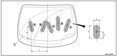
1. Black printed frame line
 : Spray area
 : Target spray position
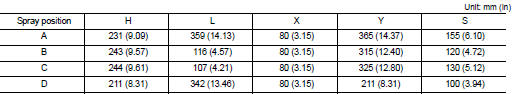
RHD models
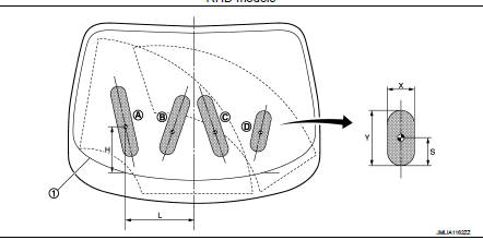
1. Black printed frame line
 : Spray area
 : Target spray position
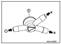
Insert a needle or similar object (A) into the spray opening (1) and move up/down and left/right to adjust the spray position.
NOTE
:
If wax or dust gets into the nozzle, remove wax or dust with a needle
or small pin.
 Washer level switch
Removal and Installation
The washer level switch must be replaced together with the washer tank as an
assembly. Refer to WW-67,
"Removal and Installation". ...
 Front wiper arm
Exploded View
RHD models
1. Front wiper arm cap
2. Front wiper arm RH
3. Front wiper drive assembly
4. Front wiper motor
5. Front wiper blade LH
6. Front wiper arm LH
7. Front wiper blad ...
Other materials:
Body side trim
Exploded View
1. Rear body side welt
2. Center pillar upper garnish
3. Front body side welt
4. Front pillar garnish
5. Metal clip
6. Dash side finisher
7. Harness clip
8. Front kicking plate inner
9. Center pillar lower garnish
10. Rear kicking plate inner
: Clip
: Pawl
: Metal ...
Hood switch
Component Function Check
1.CHECK FUNCTION
1. Select “HOOD SW” in “Data Monitor” mode of “IPDM E/R” using CONSULT-III.
2. Check “HOOD SW” indication under the following condition.
Is the indication normal?
YES >> Hood switch is OK.
NO >> Go to SEC-155, "Diagnosis Procedure& ...
Front wheel hub and knuckle
Inspection
COMPONENT PART
Check that the mounting conditions (looseness, backlash) of each component
and component conditions
(wear, damage) are normal.
WHEEL HUB ASSEMBLY (BEARING-INTEGRATED TYPE)
Check the following items, and replace the part if necessary.
• Move wheel hub assembly in ...
