Nissan Juke Service and Repair Manual : Front suspension member
Exploded View
2WD
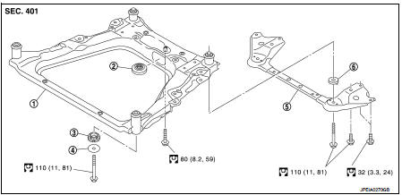
1. Front suspension member
2. Damper assembly*
3. Rebound stopper rubber
4. Washer
5. Member stay
6. Rebound stopper
 : N·m (kg-m, ft-lb)
*: For K9K models
4WD
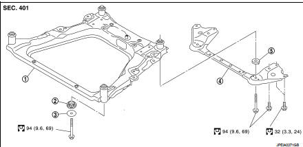
1. Front suspension member
2. Rebound stopper rubber
3. Washer
4. Member stay
5. Rebound stopper
: N·m (kg-m, ft-lb)
Removal and Installation
REMOVAL
1. Separate intermediate shaft from steering gear assembly. Refer to ST-14, "Removal and Installation".
2. Remove tires. Refer to WT-7, "Removal and Installation".
3. Remove front under cover.
4. Separate stabilizer connecting rod from strut assembly. Refer to FSU-16, "Removal and Installation".
5. Separate steering outer socket from steering knuckle. Refer to ST-19, "Removal and Installation".
6. Separate transverse link from steering knuckle.
• MR16DDT: Refer to FAX-11, "Removal and Installation".
• HR16DE: Refer to FAX-43, "Removal and Installation".
• K9K: Refer to FAX-68, "Removal and Installation".
7. Remove rear torque rod.
• MR16DDT: Refer to EM-55, "2WD : Removal and Installation".
• HR16DE: Refer to EM-215, "Removal and Installation".
• K9K: Refer to EM-326, "Removal and Installation".
8. Set suitable jack under front suspension member.
CAUTION:
Check the stable condition when using a jack.
9. Remove member stay and rebound stopper.
10. Remove suspension member mounting bolts, washer, and rebound stopper rubber.
11. Gradually lower the jack to remove front suspension member from vehicle body.
CAUTION:
Operate while checking that jack supporting status is stable.
NOTE:
Remove it with each component parts.
12. Remove damper assembly from front suspension member. (K9K models only) 13. Remove component parts from front suspension member.
14. Perform inspection after removal. Refer to FSU-14, "Inspection".
INSTALLATION
Note the following, and install in the reverse order of removal.
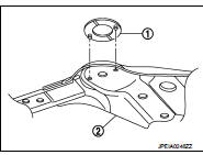
• To install rebound stopper (1), insert it with the protrusion aligned with the hole of member stay (2).
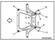
• To install member stay and mounting bolts of front suspension member, temporarily tighten the bolts before tightening to the specified torque, referring to the tightening method and the numerical order shown below:
Temporary tightening : 1 → 2 Final tightening (Specified torque) : 3 → 4 → 5 → 6 → 7 → 8 → 9 → 10 → 11 → 12
 : Vehicle front
• Perform final tightening of bolts and nuts at the vehicle installation position (rubber bushing), under unladen conditions with tires on level ground.
• Perform inspection after installation. Refer to FSU-14, "Inspection".
Inspection
INSPECTION AFTER REMOVAL
Check front suspension member for cracks, wear or damage. Replace it if necessary.
INSPECTION AFTER INSTALLATION
1. Check wheel sensor harness for proper connector.
2. Check wheel alignment. Refer to FSU-7, "Inspection".
 Front stabilizer
Exploded View
1. Stabilizer bar
2. Stabilizer clamp
3. Stabilizer bushing
4. Stabilizer connecting rod
5. Strut assembly
6. Front suspension member
: N·m (kg-m, ft-lb)
Removal and Instal ...

Other materials:
Camshaft
Exploded View
1. Camshaft position sensor (PHASE)
2. O-ring
3. Camshaft bracket
4. Camshaft (EXH)
5. Camshaft sprocket (EXH)
6. Camshaft sprocket (INT)
7. Camshaft (INT)
8. Valve lifter (EXH)
9. Valve lifter (INT)
10. Signal plate (INT)
11 Signal plate (EXH)
A.Tightening must be ...
High pressure fuel pump
Component Function Check
1.CHECK HIGH PRESSURE FUEL PUMP FUNCTION
With CONSULT-III
1. Start engine.
2. Check “FUEL PRES SEN V” in “DATA MONITOR” mode of “ENGINE” using CONSULT-III.
Without CONSULT-III
1. Start engine.
2. Check the voltage between ECM harness connector terminals as per the ...
Fuel pump
Component Function Check
1.CHECK FUEL PUMP FUNCTION
1. Turn ignition switch ON.
2. Pinch fuel feed hose with two fingers.
Fuel pressure pulsation should be felt on the fuel feed
hose for 1 second after ignition switch is turned ON.
Is the inspection result normal?
YES >> INSPECTION END
...
