Nissan Juke Service and Repair Manual : Front stabilizer
Exploded View
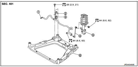
1. Stabilizer bar
2. Stabilizer clamp
3. Stabilizer bushing
4. Stabilizer connecting rod
5. Strut assembly
6. Front suspension member
 : N·m (kg-m, ft-lb)
Removal and Installation
REMOVAL
1. Remove tires. Refer to WT-7, "Removal and Installation".
2. Remove front suspension member. Refer to FSU-18, "Removal and Installation".
3. Remove stabilizer connecting rod.
4. Remove mounting bolts ( ) of
) of
stabilizer clamp, and then
remove stabilizer clamp and stabilizer bushing from front suspension
member.
5. Remove stabilizer bar.
6. Perform inspection after removal. Refer to FSU-17, "Inspection".

INSTALLATION
Note the following, and install in the reverse order of removal.
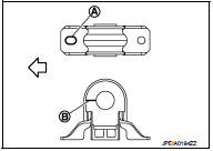
• Install stabilizer clamp and stabilizer bush with notch (A) and slit (B) faced forward of the vehicle ( ).
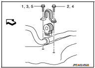
• To install stabilizer clamp mounting bolt, follow the tightening method and the numerical order shown below:
Manual tightening : 1 Temporary tightening : 2 → 3 Final tightening (Specified torque) : 4 → 5
 : Vehicle front
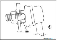
• To install stabilizer connecting rod (1), tighten the mounting nut with the hexagonal part (A) on the stabilizer connecting rod side fixed.
• Perform final tightening of bolts and nuts at the vehicle installation position (rubber bushing), under unladen conditions with tires on level ground.
• Perform inspection after installation. Refer to FSU-14, "Inspection".
Inspection
INSPECTION AFTER REMOVAL
Check stabilizer bar, stabilizer connecting rod, stabilizer bushing and stabilizer clamp for deformation, cracks or damage. Replace it if necessary.
INSPECTION AFTER INSTALLATION
Check wheel alignment. Refer to FSU-7, "Inspection".
 Transverse link
Exploded View
1. Front suspension member
2. Transverse link
: Always replace after every
disassembly.
: N·m (kg-m, ft-lb)
Removal and Installation
REMOVAL
1. Remove tires. Refer to WT-7, & ...
 Front suspension member
Exploded View
2WD
1. Front suspension member
2. Damper assembly*
3. Rebound stopper rubber
4. Washer
5. Member stay
6. Rebound stopper
: N·m (kg-m, ft-lb)
*: For K9K models
4WD
1. F ...
Other materials:
Cylinder head
Exploded View
1. Camshaft sprocket
2. Cylinder head suspended bracket
3. Valve lifter
4. Valve rotator
5. Valve spring retainer
6. Valve spring
7. Exhaust valve
8. Intake valve
9. Valve collet
10. Cap
11. Rear engine slinger
12. Cylinder head gasket
13. Cylinder head
14. Cam ...
LAN System can system (type 4)
DTC/CIRCUIT DIAGNOSIS
Main line between IPDM-E and DLC circuit
Diagnosis Procedure
1.CHECK CONNECTOR
1. Turn the ignition switch OFF.
2. Disconnect the battery cable from the negative terminal.
3. Check the following terminals and connectors for damage, bend and loose
connection (connector s ...
Component parts
Body control system
BODY CONTROL SYSTEM : Component Parts Locatio
RHD MODELS
1. BCM
A. Behind of glove box (Left side)
LHD MODELS
1. BCM
A. Behind of instrument lower panel LH
(Left side)
Power consumption control system
POWER CONSUMPTION CONTROL SYSTEM : Component Parts Location
1. ...
