Nissan Juke Service and Repair Manual : Front passenger air bag module
Exploded View
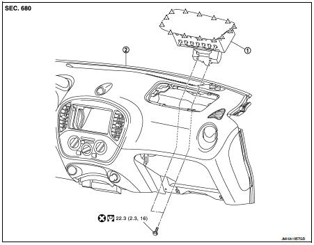
1. Front passenger air bag module 2. Instrument panel assembly
 : Pawl
 : Do not reuse
 : N·m (kg-m, ft-lb)
Removal and Installation
WARNING:
• Before servicing, turn ignition switch OFF, disconnect battery negative
terminal and wait 3 minutes
or more.
• Always work from the side of air bag module. Never work in front of it.
• Never use the air tools or the electric tools for servicing.
REMOVAL
1. Remove instrument side finisher RH, glove box lid, and glove box assembly. Refer to IP-13, "Removal and Installation".
2. Disconnect front passenger air bag module harness connector (A) from front passenger air bag module.
3. Remove front passenger air bag module fixing bolts (B).
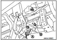
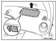
4. Put a hand to back of instrument panel (glove box opening), disengage connections of the passenger air bag module pawls from the inside of the vehicle toward the outside, and remove.
CAUTION:
• Never insert a remover tool between passenger air bag
module and instrument panel assembly. Doing so may
cause damage.
• Wear gloves.
 Pawl
Pawl
CAUTION:
• Always place the front passenger air bag module with pad
side facing upward.
 : Upward
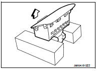
• Never impact the front passenger air bag module.
• Replace the front passenger air bag module if it has been dropped or sustained an impact.
• Never insert any foreign objects (screwdriver, etc.) into the front passenger air bag module.
• Never disassemble the front passenger air bag module.
• Never expose the front passenger air bag module to temperatures exceeding 90 °C (194 °F).
• Never allow oil, grease, detergent, or water to come in contact with the front passenger air bag module.
INSTALLATION
Note the following items, and then install in the reverse order of removal.
CAUTION:
• Never use the old fixing bolts after removal, replace with the new bolts.
• Never damage the harness while installing.
• If malfunction is detected by the air bag warning lamp, after repair or replacement of the malfunctioning parts, reset the memory using self-diagnosis or CONSULT-III. Refer to SRC-12, "On Board Diagnosis Function" or SRC-16, "CONSULT-III Function".
• After the work is completed, check that no system malfunction is detected by air bag warning lamp.
 Spiral cable
Exploded View
1. Steering column upper cover
2. Steering column assembly
3. Steering column lower cover
4. Side lid LH
5. TORX bolt
6. Driver air bag module
7. TORX bolt
8. Side lid RH ...
 Side air bag module
Exploded View
1. Side air bag module
2. Front seat assembly
: Do not reuse
: N·m (kg-m, in-lb)
Removal and Installation
WARNING:
• Before servicing, turn ignition switch OFF, disconnect batt ...
Other materials:
Rear window defogger
Description
Heats the heating wire with the power supply from the rear window defogger
relay to prevent the rear window
from fogging up.
Component Function Check
1.CHECK FUNCTION
1. Perform IPDM E/R Active Test (“REAR DEFOGGER”) using CONSULT-III.
2. Touch “ON”.
3. Check that the rear windo ...
Cowl top
Exploded View
LHD models
1. Front fender cover RH
2. Cowl top cover seal
3. Blind plug RH
4. Cowl top cover
5. Cowl top cover cap
6. Cowl top extension
7. EPT seal [t: 3.0 mm (0.118 in)]
8. Air intake cover
9. Blind plug LH
10. Front fender cover LH
11. Washer nozzle
: Clip
: ...
C1143 steering angle sensor
DTC Logic
DTC DETECTION LOGIC
DTC CONFIRMATION PROCEDURE
1.PRECONDITIONING
If “DTC CONFIRMATION PROCEDURE” has been previously conducted, always turn
ignition switch OFF and
wait at least 10 seconds before conducting the next test.
>> GO TO 2.
2.CHECK DTC DETECTION
With CONSULT ...
