Nissan Juke Service and Repair Manual : Fluid cooler system
Exploded View
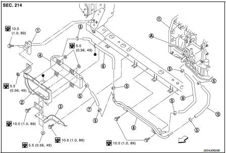
1. Bracket
2. Bracket
3. Bracket
4. CVT fluid cooler
5. Clamp
6. CVT fluid cooler hose C
7. CVT fluid cooler hose B
8. CVT fluid cooler tube assembly
9. CVT fluid cooler hose D
10. CVT fluid cooler hose A
11. Transaxle assembly
A. CVT oil warmer
 : Vehicle front
 : N·m (kg-m, in-lb)
Removal and Installation
REMOVAL
1. Remove front bumper assembly. Refer to EXT-13, "Removal and Installation".
2. Remove inlet air duct (lower). Refer to EM-161, "Removal and Installation".
3. Remove air guide (LH and RH). Refer to DLK-147, "HR16DE : Exploded View".
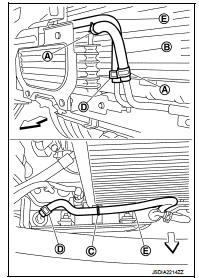
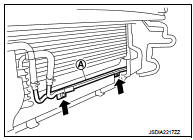
4. Remove hose clamps (A) and fluid cooler hose B (B).
 : Vehicle front
5. Disconnect clip (C) from bracket.
6. Remove hose clamps (D) and fluid cooler hose C (E).
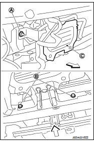
7. Remove nut (A) and bolts (B).
 : Vehicle front
8. Remove CVT fluid cooler (with brackets) (C) from the vehicle.
9. Remove clamps (A) and fluid cooler hose A (B).
 : Vehicle front
NOTE
:
Cap or plug openings to prevent fluid from spilling.
10. Remove clamps (C) and fluid cooler hose A (D).
NOTE
:
Cap or plug openings to prevent fluid from spilling.
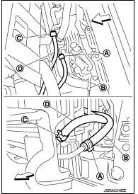
11. Remove CVT fluid cooler tube assembly (A) from the vehicle.
 : Bolt
INSTALLATION
Note the following, and Install in the reverse order of removal.
• Refer to the following when installing CVT fluid cooler hoses.
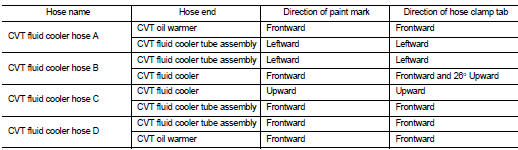
- Insert CVT fluid cooler hose according to dimension “L” described below.
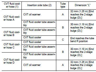
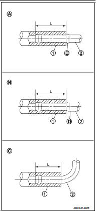
- Set hose clamps (1) at the both ends of CVT fluid cooler hoses (2) with dimension “A” from the hose edge.
Tube type A, B Dimension “A” : 5 – 9 mm (0.20 – 0.35 in) Tube type C Dimension “A” : 5 mm (0.20 in)
- Hose clamp should not interfere with the bulge of fluid cooler tube.
Inspection and Adjustment
INSPECTION AFTER INSTALLATION
Check for CVT fluid leakage. Refer to TM-480, "Inspection".
ADJUSTMENT AFTER INSTALLATION
Adjust the CVT fluid level. Refer to TM-379, "Adjustment".
 Water hose
Exploded View
1. Hose clamp
2. Water hose A
3. Water hose B
4. Water hose B
5. Water bypass pipe
6. Hose clamp
7. Heater hose
8. Water hose C
A. Water outlet
B. Heater thermostat
C ...
 Plug
Plug
Description
Replace the O-ring if oil leakage or exudes from the plug.
Exploded View
1. Plug
2. O-ring
3. O-ring
4. Plug
: Always replace after every
disassembly.
: N·m (kg-m, ft-lb)
: ...
Other materials:
B2627 outside antenna
DTC Logic
DTC DETECTION LOGIC
DTC CONFIRMATION PROCEDURE
1.PERFORM DTC CONFIRMATION PROCEDURE
1. Disconnect outside key antenna (passenger side) connector.
2. Perform “INTELLIGENT KEY” Self Diagnostic Result.
Is outside key antenna DTC detected?
YES >> Refer to DLK-63, "Diagnos ...
Check anti-pinch function
Description
If any of the following operations are performed, the initialization is
necessary for normal operation of antipinch
function.
• Disconnection and connection of battery cable from negative terminal.
• When power window main switch replaced.
• Electric power supply to power window ...
Spiral cable
Exploded View
1. Steering column upper cover
2. Steering column assembly
3. Steering column lower cover
4. Side lid LH
5. TORX bolt
6. Driver air bag module
7. TORX bolt
8. Side lid RH
9. Steering wheel
10. Spiral cable
11. Steering angle sensor
12. Combination switch
13. Stee ...
