Nissan Juke Service and Repair Manual : Exhaust manifold
Exploded View
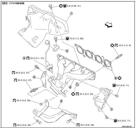
1. Exhaust manifold cover
2. Harness bracket
3. Air fuel ratio sensor 1
4. Exhaust manifold stay
5. Heat insulator
6. Exhaust manifold
7. Exhaust manifold cover
8. Gasket
 : Engine front
 : Always replace after every
disassembly.
 : N·m (kg-m, in-lb)
 : N·m (kg-m, ft-lb)
Removal and Installation
REMOVAL
1. Remove exhaust front tube. Refer to EX-12, "Exploded View".
2. Remove air duct. Refer to EM-161, "Exploded View".
3. Remove the harness bracket fixing the harness connector of the air-fuel ratio sensor from the cylinder head on the rear right side.
4. Remove exhaust manifold cover.
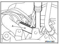
5. Remove the air fuel ratio sensor 1.
• Using heated oxygen sensor wrench [SST: KV10117100] (A), remove air fuel ratio sensor 1.
CAUTION:
• If O2 sensor is dropped on to a hard surface like a concrete
floor from a height of 0.5 m or more, discard the
sensor and use a new one.
• Clean the mounting area of O2 sensor before installing a new O2 sensor.
NOTE:
The exhaust manifold can be removed and installed without removing the air fuel ratio sensor 1 (Disassembly of harness connector is necessary).
6. Remove exhaust manifold side mounting bolt of exhaust manifold stay.
7. Remove the harness bracket of air fuel ratio sensor 1 from cylinder head.
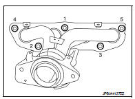
8. Remove exhaust manifold.
• Loosen nuts in reverse order as shown in the figure.
9. Remove stud bolt from cylinder head.
• Using TORX socket.
10. Remove exhaust manifold cover from exhaust manifold back side.
INSTALLATION
NOte the following, and install in the reverse order of removal.
Exhaust manifold
1. Tighten nuts in numerical order as shown in the figure.
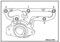
2. Tighten to the specified torque again.
Inspection
INSPECTION AFTER REMOVAL
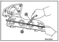
Surface Distortion
• Using feeler gauge (A) and straightedge (B), check the surface distortion of exhaust manifold mating surface in each exhaust port and entire part.
Limit : Refer to EM-251, "Exhaust Manifold".
• If it exceeds the limit, replace exhaust manifold.
 Intake manifold
Exploded View
1. EVAP canister purge volume control
solenoid valve
2. Hose clamp
3. Vacuum hose
4. Intake manifold support
5. Gasket
6. Intake manifold
7. Electric throttle control actua ...
 Oil pan (lower)
Exploded View
With Oil Cooler
1. Rear oil seal
2. O-ring
3. Oil pan (upper)
4. Oil pump chain tensioner (for oil
pump drive chain)
5. Oil pump drive chain
6. Crankshaft sprocket
7. Oil ...
Other materials:
Seat belts with pretensioners (front seats)
WARNING
• The pretensioners cannot be reused after activation. They must be replaced
together with the retractor and buckle as a unit.
• If the vehicle becomes involved in a collision but a pretensioner is not activated,
be sure to have the pretensioner system checked and, if necessary, replac ...
Keyfob battery
Component Function Check
1.CHECK FUNCTION
Check door lock and unlock operation with keyfob button.
Is the inspection result normal?
YES >> Keyfob is OK.
NO >> Refer to DLK-403, "Diagnosis Procedure".
Diagnosis Procedure
1.CHECK KEYFOB BATTERY
Check by connecting a r ...
P0037, P0038 HO2S2 heater
DTC Logic
DTC DETECTION LOGIC
DTC CONFIRMATION PROCEDURE
1.PRECONDITIONING
If DTC Confirmation Procedure has been previously conducted, always perform
the following procedure before conducting the next test.
1. Turn ignition switch OFF and wait at least 10 seconds.
2. Turn ignition switc ...
