Nissan Juke Service and Repair Manual : Exhaust manifold
Exploded View
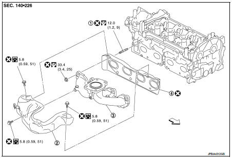
1. Stud bolt
2. Exhaust manifold cover
3. Exhaust manifold
4. Gasket
 Engine front
 : N·m (kg-m, ft-lb)
 : N·m (kg-m, in-lb)
 : Always replace after every
disassembly.
Removal and Installation
REMOVAL
1. Drain engine coolant. Refer to CO-11, "Draining".
2. Remove turbocharger. Refer to EM-36, "Exploded View".
3. Remove catalyst convertor. Refer to EM-33, "2WD : Exploded View" (2WD models) or EM-34, "4WD : Exploded View" (4WD models).
4. Remove exhaust manifold cover.
5. Remove exhaust manifold.
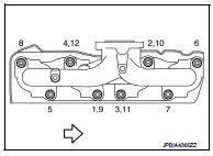
• Loosen nuts in reverse order as shown in the figure.
 : Engine front
NOTE:
Disregard the numerical order No. 9 to 12 in removal.
6. Remove gasket.
CAUTION:
Cover engine openings to avoid entry of foreign materials.
INSTALLATION
1. Install gasket to cylinder head as shown in the figure.
: Engine front
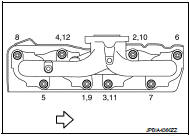
2. Install exhaust manifold with the following procedure: a. Tighten nuts in numerical order as shown in the figure.
: Engine front
NOTE
:
• Tighten nuts the No.1 to No.4 in two steps.
• The numerical order No.9 to No.12 shows the second step.
3. Install remaining parts in the reverse order of removal.
Inspection
INSPECTION AFTER REMOVAL
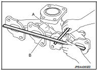
Surface Distortion
• Using feeler gauge (A) and straightedge (B), check the surface distortion
of exhaust manifold mating surface in each exhaust port
and entire part.
Limit : Refer to EM-130, "Exhaust Manifold".
• If it exceeds the limit, replace exhaust manifold.
 Turbocharger
Exploded View
1. Heat insulator
2. Actuator hose
3. Clamp
4. Turbocharger inlet tube
5. Gasket
6. Gasket
7. Clamp
8. Oil outlet hose
9. Oil return pipe
10. Oil supply tube
11. O-ri ...
 Oil pan (lower)
Exploded View
1. O-ring
2. Oil pan (upper)
3. Oil level gauge guide
4. O-ring
5. Oil level gauge
6. Oil pump drive chain
7. Crankshaft sprocket
8. Oil pump sprocket
9. Oil pump chain ...
Other materials:
Headlamp washer circuit
Component Function Check
1.CHECK HEADLAMP WASHER OPERATION
CONSULT-III ACTIVE TEST
1. Select “HEAD LAMP WASHER” of IPDM E/R active test item.
2. With operating the test item, check headlamp operation.
On :Headlamp washer ON operation
Off :Stop the headlamp washer.
Is headlamp washer operation ...
Line pressure test
Work Procedure
INSPECTION
1. Check the engine oil level. Replenish if necessary. LU-25, "Inspection".
2. Check for leak of the CVT fluid. Refer to TM-480, "Inspection".
3. Drive for about 10 minutes to warm up the vehicle so that the CVT fluid
temperature is 50 to 80°C (122 ...
Camshaft
*: Total indicator readin
VALVE LIFTER
VALVE CLEARANCE
*: Approximately 80°C (176°F)
AVAILABLE VALVE LIFTER
...
