Nissan Juke Service and Repair Manual : Engine stand setting
NOTE
:
Explained here is how to disassemble with engine stand supporting transaxle
surface. When using different
type of engine stand, note with difference in steps and etc.
1. Remove the engine and the transaxle assembly from the vehicle, and separate the transaxle from the engine. Refer to EM-215, "Exploded View".
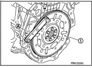
2. Install engine to engine stand with the following procedure: a. Remove flywheel or drive plate.
• Secure flywheel (1) with a stopper plate [SST: KV11105210] (A), and remove mounting bolts (M/T models).
![• Secure driveplate (1) with a stopper plate [SST: KV11105210]](images/books/335/5/index.127.jpg)
• Secure driveplate (1) with a stopper plate [SST: KV11105210] (A), and remove mounting bolts (CVT models).
CAUTION:
• Never disassemble them.
• Never place them with signal plate facing down.
• When handling signal plate, take care not to damage or scratch them.
• Handle signal plate in a manner that prevents them from becoming magnetized.
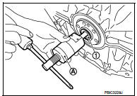
b. Remove pilot converter (1) from the rear end of the crankshaft.
Use a pilot bush puller [SST: ST16610000] (A), if necessary.
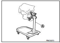
c. Lift the engine with a hoist to install it onto widely use engine stand.
CAUTION
:
• Use the engine stand that has a load capacity [approximately 150 kg (331
lb) or more] large
enough for supporting the engine weight.
• If the load capacity of stand is not adequate, remove the following parts beforehand to reduce the potential risk of overturning stand.
- Intake manifold: Refer to EM-163, "Exploded View".
- Exhaust manifold: Refer to EM-166, "Removal and Installation".
- Rocker cover: Refer to EM-178, "Exploded View".
NOTE
:
The figure shows an example of widely used engine stand (A)
that can support mating surface of transaxle with flywheel
removed.
CAUTION:
Before removing the hanging chains, check the engine
stand is stable and there is no risk of overturning.
3. Drain engine oil. Refer to LU-26, "Draining".
CAUTION:
Be sure to clean drain plug and install with new drain plug washer.
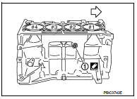
4. Drain engine coolant by removing water drain plug (1) from inside of the engine.
 : Engine front
Tightening torque : Refer to EM-227, "Exploded View".
Use Genuine Liquid Gasket or equivalent.

 Engine unit
Disassembly
1. Remove intake manifold. Refer to EM-163, "Exploded View".
2. Remove exhaust manifold. Refer to EM-166, "Exploded View".
3. Remove oil pan (lower). Refer to EM-16 ...
Other materials:
Drive pinion
Exploded View
1. Pinion lock nut
2. Companion flange
3. Drive pion oil seal
4. Pinon rear bearing
5. Transfer case
6. Gasket
7. Filler plug
8. Collapsible spacer
9. Drive pinion adjust shim
10. Drive pinion
11. Pinion front bearing
12. Ring gear
13. Ring gear shaft
14. Ring ...
B1033, B1034 crash zone sensor
DTC Logic
DTC DETECTION LOGIC
DTC CONFIRMATION PROCEDURE
1.CHECK SELF-DIAG RESULT
With CONSULT-III
1. Turn ignition switch ON.
2. Perform “Self Diagnostic Result” mode of “AIR BAG” using CONSULT-III.
Without CONSULT-III
1. Turn ignition switch ON.
2. Check the air bag warning lamp statu ...
Off-road recovery
If the right side or left side wheels leave the road surface, maintain control
of the vehicle by following the procedure below. Please note that this procedure
is only a general guide. The vehicle must be driven as appropriate based on the
conditions of the vehicle, road and traffic.
1. Remai ...
