Nissan Juke Service and Repair Manual : Electrical load signal
Description
The electrical load signal (Headlamp switch signal, rear window defogger switch signal, etc.) is transferred via the CAN communication line.
Component Function Check
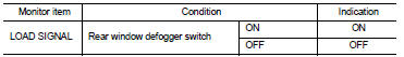
1.CHECK REAR WINDOW DEFOGGER SWITCH FUNCTION
 With CONSULT-III
1. Turn ignition switch ON.
2. Select “DATA MONITOR” mode of “ENGINE” using CONSULT-III.
3. Select “LOAD SIGNAL” and check indication as per the following conditions.
Is the inspection result normal? YES >> GO TO 2.
NO >> Proceed to EC-418, "Diagnosis Procedure".
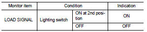
2.CHECK LIGHTING SWITCH FUNCTION
 With CONSULT-III
Check “LOAD SIGNAL” indication as per the following conditions.
Is the inspection result normal? YES >> GO TO 3.
NO >> Proceed to EC-418, "Diagnosis Procedure".
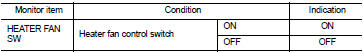
3.CHECK HEATER FAN CONTROL SWITCH FUNCTION
 With CONSULT-III
Select “HEATER FAN SW” and check indication as per the following conditions.
Is the inspection result normal? YES >> INSPECTION END
NO >> Proceed to EC-418, "Diagnosis Procedure".
Diagnosis Procedure
1.INSPECTION START
Confirm the malfunctioning circuit (rear window defogger, headlamp or heater fan). Refer to EC-418, "Component Function Check".
Which circuit is related to the incident? Rear window defogger>>GO TO 2.
Headlamp>>GO TO 3.
Heater fan>>GO TO 4.
2.CHECK REAR WINDOW DEFOGGER SYSTEM
Check the rear window defogger system. Refer to DEF-25, "Work Flow".
>> INSPECTION END 3.CHECK HEADLAMP SYSTEM
Check the headlamp system. Refer to EXL-43, "Work Flow".
>> INSPECTION END 4.CHECK HEATER FAN CONTROL SYSTEM
Check the heater fan control system. refer to HA-72, "Work Flow".
>> INSPECTION END
 Ignition signal
Component Function Check
1.INSPECTION START
Turn ignition switch OFF, and restart engine.
Does the engine start?
YES >> GO TO 2.
NO >> Proceed to EC-414, "Diagnosis Procedure ...
 Cooling fan
Component Function Check
1.CHECK COOLING FAN FUNCTION
With CONSULT-III
1. Turn ignition switch ON.
2. Perform “FAN DUTY CONTROL” in “ACTIVE TEST” mode of “ENGINE” using
CONSULT-III.
3. Check th ...
Other materials:
Drive pinion
Exploded View
1. Filler plug
2. Gasket
3. Drain plug
4. Breather tube
5. Clip
6. Breather hose
7. Breather
8. sub-harness clip
9. sub-harness
10. Rear cover
11. Center stem
12. Side bearing (right)
13. Side bearing adjusting shim (right)
14. Side oil seal (right)
15. Conne ...
Precaution for Supplemental Restraint System (SRS) "AIR BAG" and "SEAT BELT
PRE-TENSIONER"
The Supplemental Restraint System such as “AIR BAG” and “SEAT BELT PRE-TENSIONER”,
used along
with a front seat belt, helps to reduce the risk or severity of injury to the
driver and front passenger for certain
types of collision. Information necessary to service the system safely is
include ...
Lower link
Exploded View
1. Rear suspension member
2. Adjusting bolt
3. Upper link
4. Eccentric disk
5. Lower link
6. Suspension arm bracket
7. Suspension arm
: Vehicle front
: Always replace after every
disassembly.
: N·m (kg-m, ft-lb)
Removal and Installation
REMOVAL
1. Remove tires. Ref ...
