Nissan Juke Service and Repair Manual : Electric controlled coupling oil seal
Exploded View
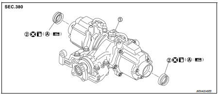
1. Rear final drive assembly 2. Electric controlled coupling oil seal
A. Oil seal lip
 : Vehicle front
 : Always replace after every
disassembly.
 : Apply multi purpose grease
 : Apply gear oil.
Removal and Installation
REMOVAL
1. Remove rear drive shafts. Refer to RAX-17, "Removal and Installation".
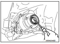
2. Remove electric controlled coupling oil seals from electric controlled coupling, using a suitable tool.
CAUTION:
Never damage electric controlled coupling.
INSTALLATION
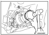
1. Install electric controlled coupling oil seals to electric controlled coupling, using the drift (A) (SST: KV38109700).
NOTE
:
The use of the special service tool satisfies the mounting dimensions.
CAUTION:
• Never reuse oil seals.
• When installing, never incline oil seals.
• Apply multi-purpose grease onto oil seal lips, and gear oil onto the circumference of oil seal.
2. Install rear drive shafts. Refer to RAX-17, "Removal and Installation".
3. When oil leaks while removing, check oil level after the installation. Refer to DLN-132, "Inspection".
 Electric controlled coupling
Exploded View
1. Sub-harness
2. Rear final drive assembly
3. Electric controlled coupling (right)
4. Reamer bolt
5. Electric controlled coupling (left)
A. Gear carrier mouting face
: Vehic ...
 Unit removal and installation
REAR FINAL DRIVE ASSEMBLY ...
Other materials:
Charging system preliminary inspection
Inspection Procedure
1.CHECK BATTERY TERMINALS CONNECTION
Check if battery terminals are clean and tight.
Is the inspection result normal?
YES >> GO TO 2.
NO >> Repair battery terminals connection.
2.CHECK FUSE
Check for blown fuse and fusible link.
Is the inspection resu ...
Super lock does not operate
All door
ALL DOOR : Diagnosis Procedure
1.CHECK SUPER LOCK ACTUATOR
Check front driver side super lock actuator.
Refer to DLK-99, "DRIVER SIDE : Component Function Check".
Is the inspection result normal?
YES >> GO TO 2.
NO >> Repair or replace the malfunctioning p ...
Exploded View
M/T models
1. Clamp
2. Water hose
3. Oil cooler
4. Water hose
N·m (kg-m, in-lb)
CVT models
1. Clamp
2. Water hose
3. Oil cooler
4. Water hose
5. Water hose
6. Heater thermostat
7. Water hose
A. To CVT oil warmer
: N·m (kg-m, in-lb)
...
