Nissan Juke Service and Repair Manual : Ecu diagnosis information
BCM
Reference Value
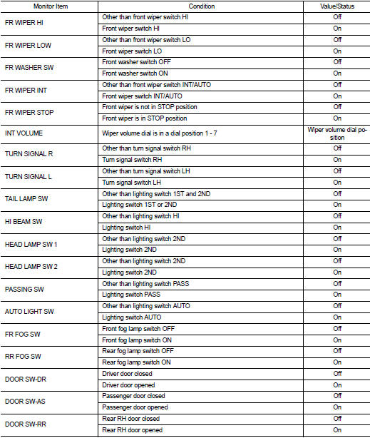
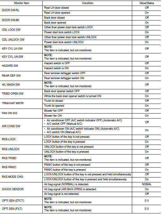
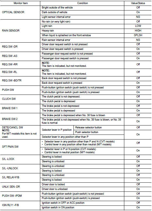
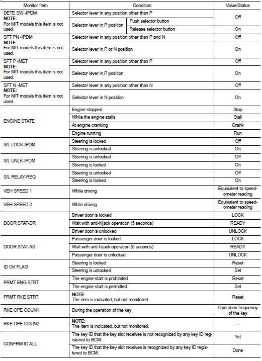
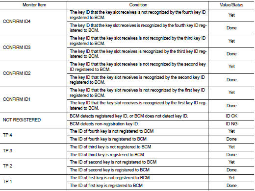
VALUES ON THE DIAGNOSIS TOOL
CONSULT-III MONITOR ITEM
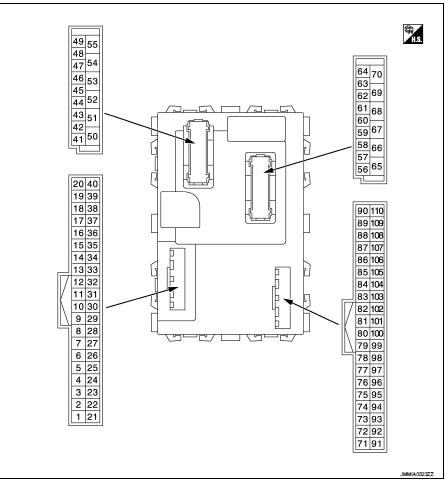
TERMINAL LAYOUT
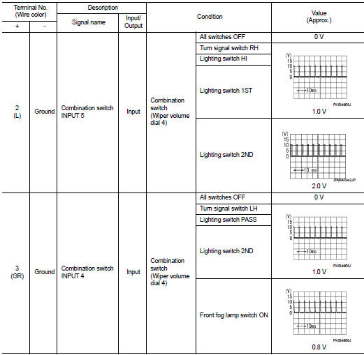
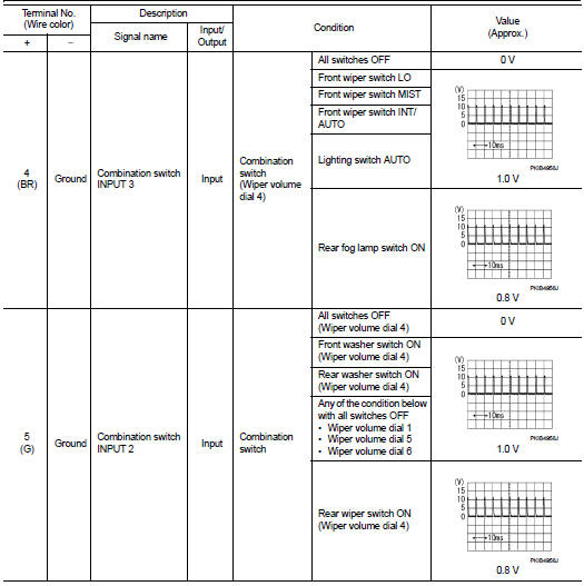
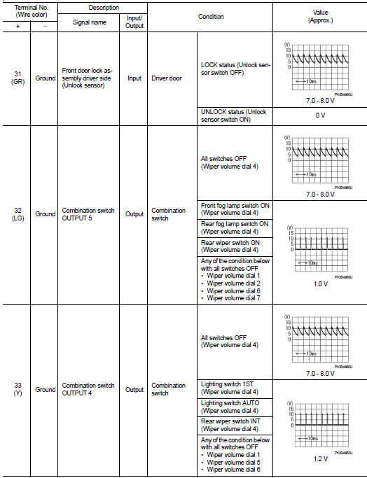
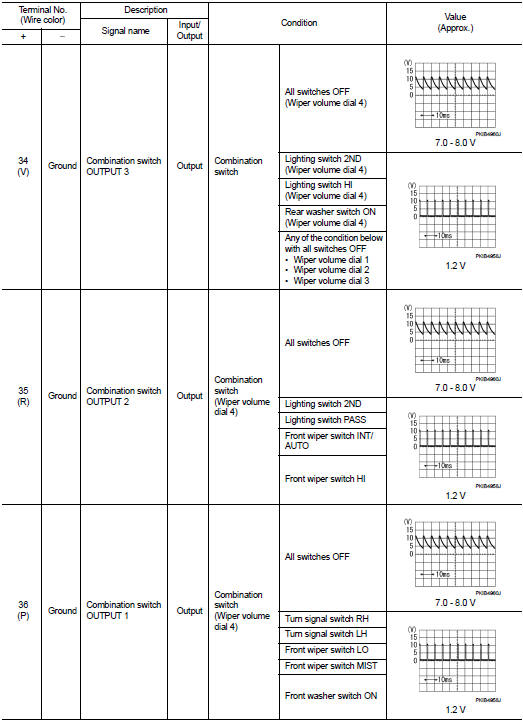
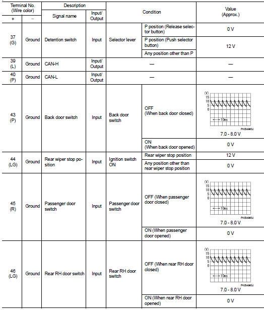
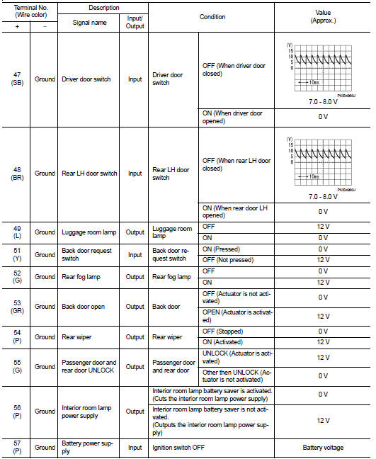
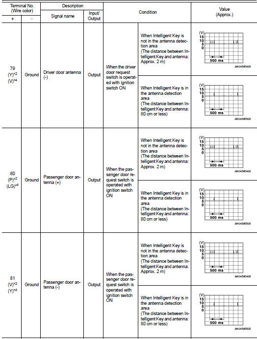
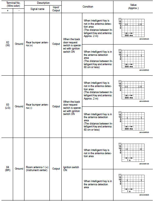
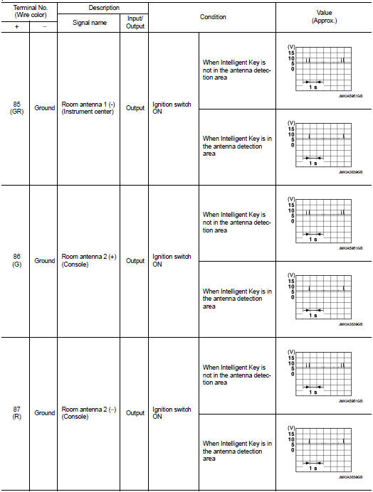
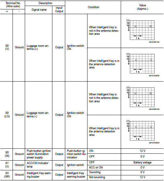
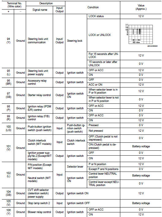
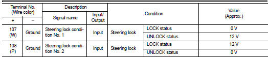
PHYSICAL VALUES
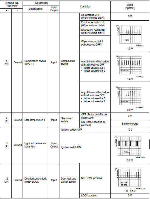
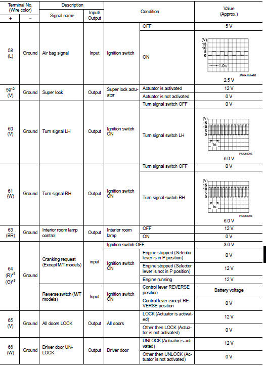
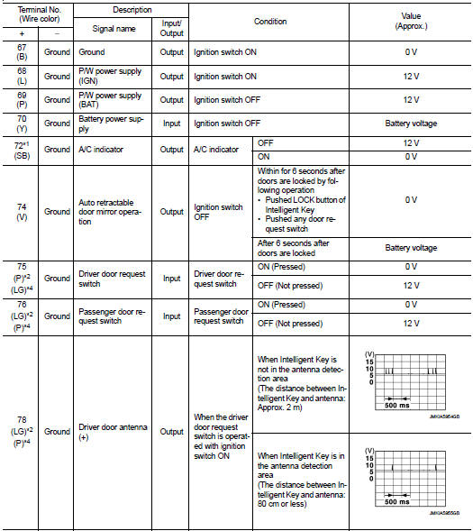
• *1: With manual A/C
• *2: RHD models
• *3: M/T models
• *4: LHD models
• *5: Except M/T models
Fail-safe
FAIL-SAFE CONTROL BY DTC
BCM performs fail-safe control when any DTC are detected.
REAR WIPER MOTOR PROTECTION
BCM detects the rear wiper stopping position according to the rear wiper stop position signal.
When the rear wiper stop position signal does not change for more than 5 seconds while driving the rear wiper, BCM stops power supply to protect the rear wiper motor.
Condition of cancellation 1. More than 1 minute is passed after the rear wiper stop.
2. Turn rear wiper switch OFF.
3. Operate the rear wiper switch or rear washer switch.
FAIL-SAFE CONTROL BY LIGHT AND RAIN SENSOR MALFUNCTION
BCM detects the light and rain sensor serial link error and the light and rain sensor malfunction.
BCM controls the following fail-safe when light and rain sensor has a malfunction.
Fail-safe Control
• Auto light control: Headlamp low beam, parking lamp, license plate lamp and
tail lamp are turned ON.
• Front wiper control
- Front wiper switch AUTO and sensing rain drop: The condition just before the
activation of fail-safe is maintained
until the front wiper switch is turned OFF.
- Front wiper switch AUTO and not sensing rain drop: Front wiper is LO operation until the front wiper switch is turned off.
FAIL-SAFE CONTROL OF COMBINATION SWITCH READING FUNCTION CAUSED BY LOW POWER SUPPLY VOLTAGE
If voltage of battery power supply lower, BCM maintains combination switch reading to the status when input voltage is less than approximately 9 V.
NOTE
:
When voltage of battery power supply is approximately 9 V or more, combination
switch reading function
returns to normal operation
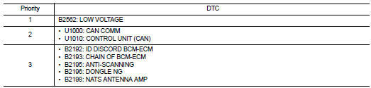
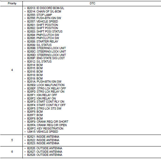
DTC Inspection Priority Chart
If some DTCs are displayed at the same time, perform inspections one by one based on the following priority chart.
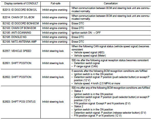
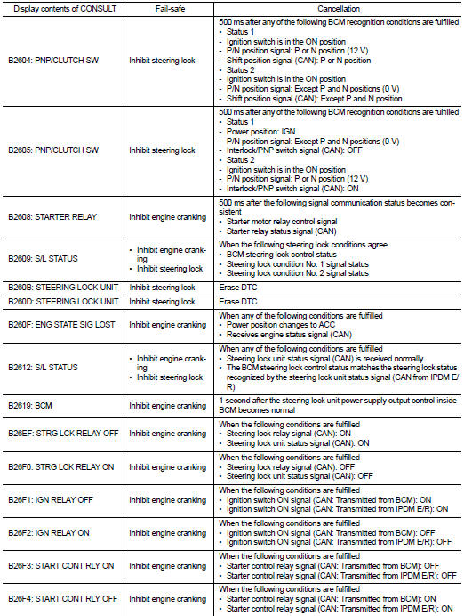
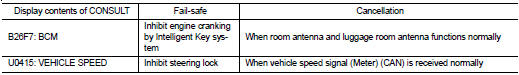
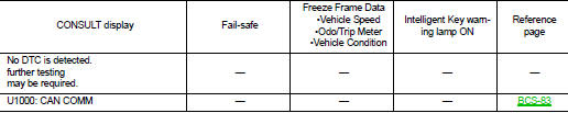
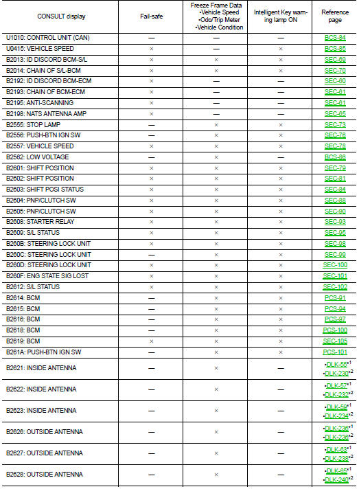
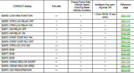
DTC Index
NOTE
:
The details of time display are as follows.
• CRNT: A malfunction is detected now.
• PAST: A malfunction was detected in the past.
IGN counter is displayed on Freeze Frame Data. For details of Freeze Frame Data, refer to BCS-17, "COMMON ITEM : CONSULT-III Function (BCM - COMMON ITEM)".
NOTE
:
• *1: With super lock
• *2: Without super lock
 Diagnosis system (BCM)
Common item
COMMON ITEM : CONSULT-III Function (BCM - COMMON ITEM)
APPLICATION ITEM
CONSULT-III performs the following functions via CAN communication with BCM.
SYSTEM APPLICATION
BCM can perfo ...
 Wiring diagram
BCM
LHD
LHD : Wiring Diagram
For connector terminal arrangements, harness layouts, and alphabets in a
(option abbreviation; if not
described in wiring diagram), refer to GI-12, "Connector I ...
Other materials:
Intake valve timing control
Intake valve timing control : System Diagram
Intake valve timing control : System Description
INPUT/OUTPUT SIGNAL CHART
SYSTEM DESCRIPTION
This mechanism hydraulically controls cam phases continuously with the fixed
operating angle of the intakevalve.
The ECM receives signals such as ...
Additional service when removing battery negative terminal
Description
• The NAVI control unit is equipped with the anti-theft system.
• The NAVI control unit operates after authenticating a fixed four-digit
anti-theft code.
• After removing the battery of the NAVI control unit, the authentication of the
anti-theft code is required.
Work Procedure
...
Stop lamp switch
Component Function Check
1.CHECK STOP LAMP SWITCH OPERATION
Depress brake pedal and check that stop lamp turns ON, or release brake pedal
and check stop lamp turns
OFF.
Is the inspection result normal?
YES >> GO TO 2.
NO >> Check stop lamp system. Refer to EXL-39, "Wirin ...
