Nissan Juke Service and Repair Manual : Drive belt
Checking
• Inspection should be done only when engine is cold or over 30 minutes after the engine is stopped.
1 : Alternator
2 : Water pump
3 : Crankshaft pulley
4 : A/C compressor
5 : Idler pulley
6 : Drive belt
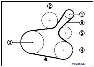
• Visually check belts for wear, damage, and cracks on inside and edges.
• Turn crankshaft pulley two time clockwise, and check tension on all pulleys is equal before doing the test.
• When measuring deflection, apply 98 N (10 kg, 22 lb) at the (
 ) marked point.
• Measure the belt tension and frequency with acoustic tension gauge (commercial
service tool) at the ( )
marked point.
CAUTION:
• When the tension and frequency are measured, the acoustic tension gauge should
be used.
• When checking immediately after installation, first adjust it to the specified value. Then, after turning crankshaft two turns or more, readjust to the specified value to avoid variation in deflection between pulleys.
Belt Deflection/Belt Tension and Frequency: Refer to EM-250, "Drive Belt".
Tension Adjustment

CAUTION:
• When belt is replaced with new one, adjust belt tension to the value for “New
belt”, because new belt
will not fully seat in the pulley groove.
• When tension of the belt being used exceeds “Limit”, adjust it to the value for “After adjusted”.
• When installing a belt, check it is correctly engaged with the pulley groove.
• Never allow oil or engine coolant to get on the belt.
• Never twist or bend the belt strongly.
1. Remove front fender protector (RH). Refer to EXT-22, "Exploded View".
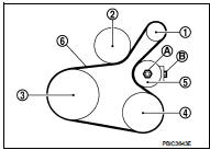
2. After loosening lock nut (A) of idler pulley (5) to release from the specified torque state, temporarily tighten the lock nut to the following torque
 4.4 N·m (0.45 kg-m, 39 in-lb)
1 : Alternator
2 : Water pump
3 : Crankshaft pulley
4 : A/C compressor
5 : Idler pulley
6 : Drive belt
CAUTION:
• When the lock nut is loosened excessively, the idler pulley tilts and the
correct tension adjustment
cannot be performed. Never loosen it excessively (more than 45 degrees).
• Put a matching mark on the lock nut (A), and check turning angle with a protractor. Never visually check the tightening angle.
3. Adjust the belt tension by turning the adjusting bolt (B). Refer to EM-154, "Checking".
CAUTION:
• When checking immediately after installation, first adjust it to the specified
value. Then, after
turning crankshaft two turns or more, readjust to the specified value to avoid
variation in deflection
between pulleys.
• When the tension adjustment is performed, the lock nut should be in the condition at step“ 2”. If the tension adjustment is performed when the lock nut is loosened more than the standard, the idler pulley tilts and the correct tension adjustment cannot be performed.
4. Tighten the lock nut.
: 34.8 N·m (3.5 kg-m, 26 ft-lb)
Removal and Installation
REMOVAL
1. Remove front fender protector (RH). Refer to EXT-22, "Exploded View".
2. Loosen the lock nut (A), and then adjust the belt tension by turning the adjusting bolt (B).
1 : Alternator
2 : Water pump
3 : Crankshaft pulley
4 : A/C compressor
5 : Idler pulley
6 : Drive belt
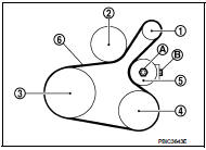
3. Remove drive belt.
INSTALLATION
1. Pull the idler pulley in the loosening direction, and then temporarily tighten the lock nut (A) to the following torque.
1 : Alternator
2 : Water pump
3 : Crankshaft pulley
4 : A/C compressor
5 : Idler pulley
6 : Drive belt
: 4.4 N·m (0.45 kg-m, 39 in-lb)
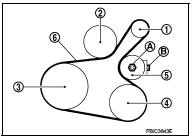
NOTE
:
Do not move the lock nut from the tightened position. Go to step “2”.
2. Install the drive belt to each pulley.
CAUTION:
• Check that there is no oil, grease, or coolant, etc. in pulley grooves.
• Check that the belt is securely inside the groove on each pulley.
3. Adjust drive belt tension by turning the adjusting bolt (B). Refer to EM-154, "Tension Adjustment".
CAUTION
:
• Perform the belt tension adjustment with the lock nut temporarily tightened
at the step “1” so as
not to tilt the idler pulley.
• When checking immediately after installation, first adjust it to the specified value. Then, after turning crankshaft two turns or more, readjust to the specified value to avoid variation in deflection between pulleys.
4. Tighten the lock nut.
: 34.8 N·m (3.5 kg-m, 26 ft-lb)
5. Check that belt tension of each belt within the standard.

 Air cleaner filter
Exploded View
1. Hose clamp
2. PCV hose
3. Hose clamp
4. Air cleaner filter
5. Air cleaner filter case
6. Grommet
7. Inlet Air duct (lower)
8. Grommet
9. Inlet Air duct (upper)
10. B ...
Other materials:
Horn function
Component Function Check
1.CHECK FUNCTION 1
1. Disconnect vehicle security horn relay.
2. Perform “VEHICLE SECURITY HORN” in “ACTIVE TEST” mode of “THEFT ALM” of “BCM”
using CONSULT-
III.
3. Check the horn operation.
Is the operation normal?
YES >> GO TO 2.
NO >> Go to SEC- ...
Combination switch output circuit
Diagnosis Procedure
1.CHECK OUTPUT 1 - 5 CIRCUIT FOR OPEN
1. Turn ignition switch OFF.
2. Disconnect BCM and combination switch connectors.
3. Check continuity between BCM harness connector and combination switch harness
connector
Does continuity exist?
YES >> GO TO 2.
NO >> ...
ANTI-HIJACK function does not operate
Diagnosis Procedure
1.CHECK “DOOR LOCK–UNLOCK SET” SETTING IN “WORK SUPPORT”
1. Select “DOOR LOCK” of “BCM” using CONSULT-III.
2. Select “DOOR LOCK-UNLOCK SET” in “WORK SUPPORT” mode.
3. Check “DOOR LOCK-UNLOCK SET” in “WORK SUPPORT”
Refer to DLK-371, "DOOR LOCK : CONSULT-III Function (BCM ...
