Nissan Juke Service and Repair Manual : Drive belt
Exploded View
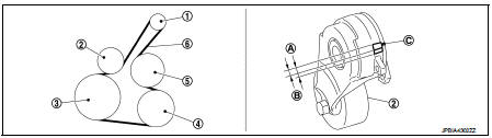
1. Alternator
2. Drive belt auto-tensioner
3. Crankshaft pulley
4. A/C compressor
5. Water pump
6. Drive belt
A. Possible use range B.
Range when new drive belt is installed C. Indicator
Checking
WARNING
: Perform this step when engine is stopped.
• Check that the indicator (C) (notch on fixed side) of drive belt auto-tensioner is within the possible use range (A) in the figure.
NOTE
:
• Check the drive belt auto-tensioner indication when the engine is cold.
• When new drive belt is installed, the indicator (notch on fixed side) should be within the range (B) in the figure.
• Visually check entire drive belt for wear, damage or cracks.
• If the indicator (notch on fixed side) is out of the possible use range or belt is damaged, replace drive belt.
Tension Adjustment
Refer to : EM-129, "Drive Belt".
Removal and Installation
REMOVAL
1. Turn the steering wheel to the right.
2. Remove the front fender protector (RH) front side bolts and clips. And keep a service area. Refer to EXT- 22, "Exploded View".
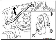
3. Hold the hexagonal part (A) of drive belt auto-tensioner (1) with a wrench securely. Then move the wrench handle in the direction of arrow (loosening direction of tensioner).
CAUTION
:
Avoid placing hand in a location where pinching may occur if the holding tool accidentally comes off
.
4. Insert a rod approximately 6 mm (0.24 in) in diameter such as short-length screwdriver into the hole (B) of the retaining boss to fix drive belt auto-tensioner.
• Keep drive belt auto-tensioner pulley arm locked after drive belt is removed.
5. Remove drive belt.
INSTALLATION
1. Install drive belt.
CAUTION
:
• Confirm drive belt is completely set to pulleys.
• Check for engine oil, working fluid and engine coolant are not adhered to drive belt and each pulley groove
.
2. Release drive belt auto-tensioner, and apply tension to drive belt.
3. Turn crankshaft pulley clockwise several times to equalize tension between each pulley.
4. Confirm tension of drive belt at indicator (notch on fixed side) is within the possible use range. Refer to EM-20, "Exploded View".

 Air cleaner filter
Removal and Installation
REMOVAL
1. Remove air duct assembly (duct side) (1).
2. Unhook the tabs (A) of both ends of the air cleaner cover.
3. Remove the air cleaner filter (1) and air cleaner b ...
Other materials:
Radiator cap : Inspection
Check valve seat (A) of radiator cap.
B : Metal plunger
- Check that valve seat is swollen to the extent that the edge of the
plunger cannot be seen when watching it vertically from the top.
- Check that valve seat has no soil and damage.
Pull negative-pressure valve to open it, and that it c ...
P0848 transmission fluid pressure SEN/SW B
DTC Logic
DTC DETECTION LOGIC
DTC CONFIRMATION PROCEDURE
1.PREPARATION BEFORE WORK
If another "DTC CONFIRMATION PROCEDURE" occurs just before, the ignition
switch OFF and wait for at
least 10 seconds, then perform the next test.
>> GO TO 2.
2.CHECK DTC DETECTION
With ...
Booster seats
Precautions on booster seats
WARNING
If a booster seat and seat belt are not used properly, the risk of a child
being injured in a sudden stop or collision greatly increases:
• Make sure the shoulder portion of the belt is away from the child’s face
and neck and the lap portion of the belt do ...
