Nissan Juke Service and Repair Manual : Door request switch
Component Function Check
1.CHECK FUNCTION
1. Select “INTELLIGENT KEY” of “BCM” using CONSULT-III.
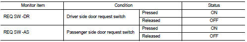
2. Select “REQ SW-DR”, “REQ SW-AS” in “DATA MONITOR” mode.
3. Check that the function operates normally according to the following conditions.
Is the inspection result normal? YES >> Front door request switch is OK.
NO >> Refer to DLK-256, "Diagnosis Procedure".
Diagnosis Procedure
1.CHECK DOOR REQUEST SWITCH INPUT SIGNAL
1. Turn ignition switch OFF.
2. Disconnect malfunctioning front door request switch connector.
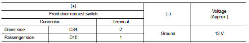
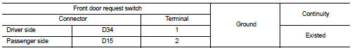
3. Check voltage between malfunctioning front door request switch harness connector and ground.
Is the inspection result normal? YES >> GO TO 3.
NO >> GO TO 2.
2.CHECK DOOR REQUEST SWITCH CIRCUIT
1. Disconnect BCM connector.
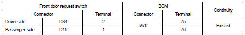
2. Check continuity between malfunctioning front door request switch harness connector and BCM harness connector.
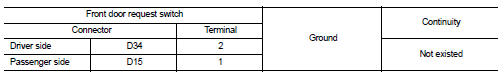
3. Check continuity between malfunctioning front door request switch harness connector and ground.
Is the inspection result normal? YES >> Replace BCM. Refer to BCS-93, "Removal and Installation".
NO >> Repair or replace harness.
3.CHECK DOOR REQUEST SWITCH GROUND CIRCUIT
Check continuity between malfunctioning front door request switch harness connector and ground.
Is the inspection result normal? YES >> GO TO 4.
NO >> Repair or replace harness.
4.CHECK DOOR REQUEST SWITCH
Refer to DLK-257, "Component Inspection".
Is the inspection result normal? YES >> GO TO 5.
NO >> Replace malfunctioning front door request switch.
5.CHECK INTERMITTENT INCIDENT
Refer to GI-42, "Intermittent Incident".
>> INSPECTION END
Component Inspection
1.CHECK DOOR REQUEST SWITCH
1. Turn ignition switch OFF.
2. Disconnect malfunctioning front door request switch connector.
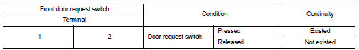
3. Check continuity between malfunctioning front door request switch terminals.
Is the inspection result normal? YES >> INSPECTION END
NO >> Replace malfunctioning front door request switch.
 Door lock and unlock switch
Component Function Check
1.CHECK FUNCTION
1. Select “DOOR LOCK” of “BCM” using CONSULT-III.
2. Select “CDL LOCK SW”, “CDL UNLOCK SW” in “DATA MONITOR” mode.
3. Check that the function operates nor ...
 Door switch
Component Function Check
1.CHECK FUNCTION
1. Select “DOOR LOCK” of “BCM” using CONSULT-III.
2. Select “DOOR SW-DR”, “DOOR SW-AS”, “DOOR SW-RL”, “DOOR SW-RR”, “DOOR SW-BK”
in “DATA
MONITOR” mode. ...
Other materials:
P2118 throttle control motor
DTC Logic
DTC DETECTION LOGIC
DTC CONFIRMATION PROCEDURE
1.PRECONDITIONING
If DTC Confirmation Procedure has been previously conducted, always turn
ignition switch OFF and wait at
least 10 seconds before conducting the next test.
>> GO TO 2.
2.PERFORM DTC CONFIRMATION PROCEDURE
...
Diagnosis and repair workflow
Work Flow
OVERALL SEQUENCE
DETAILED FLOW
1.INTERVIEW FOR MALFUNCTION
Interview the symptom to the customer.
>> GO TO 2.
2.SYMPTOM CHECK
Check the symptom from the customer's information.
>> GO TO 3.
3.BASIC INSPECTION
Check the operation of each part. Check that any s ...
P0470 exhaust gas pressure sensor 1
DTC Logic
DTC DETECTION LOGIC
NOTE:
If DTC P0470 is displayed with DTC P0651 or P2263, first perform trouble
diagnosis for DTC P0651 or P2263.
Refer to EC-975, "DTC Logic" (P0651), EC-1003, "DTC Logic" (P2263).
Diagnosis Procedure
1.CHECK GROUND CONNECTIONS
1. Turn i ...
