Nissan Juke Service and Repair Manual : Door mirror defogger
Description
Heats the heating wire with the power supply from the rear window defogger relay to prevent the door mirror from fogging up.
Component Function Check
1.CHECK DOOR MIRROR DEFOGGER
1. Perform IPDM E/R Active Test (“REAR DEFOGGER”) using CONSULT-III.
2. Touch “ON”.
3. Check that both side door mirror glasses are getting warmer.
Is the inspection result normal? YES >> Door mirror defogger is OK.
NO >> Refer to DEF-34, "Diagnosis Procedure"
Diagnosis Procedure
1.CHECK FUSE
1. Turn ignition switch OFF.
2. Check 10A fuse [No.22, located in fuse block (J/B)].
Is the inspection result normal? YES >> GO TO 2.
NO >> Replace the blown fuse after repairing the affected circuit if a fuse is blown.
2.CHECK DOOR MIRROR DEFOGGER CIRCUIT
1. Disconnect IPDM E/R connector and door mirror (both sides) connector.
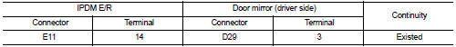
2. Check continuity between IPDM E/R harness connector and door mirror (driver side) harness connector.
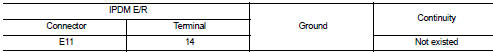
3. Check continuity between IPDM E/R harness connector and ground.
Is the inspection result normal? YES >> GO TO 3.
NO >> Repair or replace harness.
3.CHECK INTERMITTENT INCIDENT
Check intermittent incident.
Refer to GI-42, "Intermittent Incident".
>> INSPECTION END
 Rear window defogger
Description
Heats the heating wire with the power supply from the rear window defogger
relay to prevent the rear window
from fogging up.
Component Function Check
1.CHECK FUNCTION
1. Perform IPD ...
 Driver side door mirror defogger
Description
Heats the heating wire with the power supply from the rear window defogger
relay to prevent the door mirror
from fogging up.
Component Function Check
1.CHECK DRIVER SIDE DOOR MIRROR ...
Other materials:
Symptom diagnosis
Squeak and rattle trouble diagnoses
Work Flow
CUSTOMER INTERVIEW
Interview the customer if possible, to determine the conditions that exist
when the noise occurs. Use the Diagnostic
Worksheet during the interview to document the facts and conditions when the
noise occurs and any of
the cu ...
Lower link
Exploded View
1. Rear suspension member
2. Adjusting bolt
3. Upper link
4. Eccentric disk
5. Lower link
6. Suspension arm bracket
7. Suspension arm
: Vehicle front
: Always replace after every
disassembly.
: N·m (kg-m, ft-lb)
Removal and Installation
REMOVAL
1. Remove tires. Ref ...
Precaution Necessary for Steering Wheel Rotation after Battery Disconnect
NOTE:
• Before removing and installing any control units, first turn the ignition
switch to the LOCK position, then disconnect
both battery cables.
• After finishing work, confirm that all control unit connectors are connected
properly, then re-connect both
battery cables.
• Always use CONS ...
