Nissan Juke Service and Repair Manual : Door lock status indicator
Component Function Check
1.CHECK FUNCTION
1. Select “DOOR LOCK” of “BCM” using CONSULT-III.
2. Select “DOOR LOCK IND” in “ACTIVE TEST” mode.
3. Check that the function operates normally according to the following conditions.
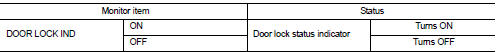
Is the inspection result normal? YES >> Door lock status indicator is OK.
NO >> Refer to DLK-83, "Diagnosis Procedure".
Diagnosis Procedure
1.CHECK DOOR LOCK STATUS INDICATOR INPUT SIGNAL
1. Turn ignition switch OFF.
2. Disconnect door lock status indicator connector.
3. Check voltage between door lock status indicator harness connector and ground.
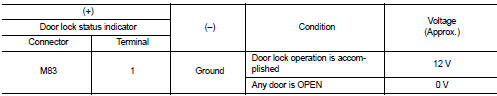
Is the inspection result normal? YES >> GO TO 3.
NO >> GO TO 2.
2.CHECK DOOR LOCK STATUS INDICATOR CIRCUIT
1. Disconnect BCM connector.
2. Check continuity between BCM harness connector and door lock status indicator harness connector.
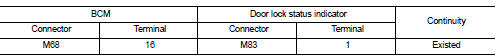
3. Check continuity between BCM harness connector and ground.
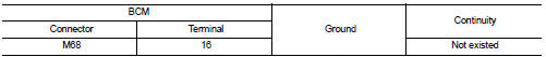
Is the inspection result normal? YES >> Replace BCM. Refer to BCS-93, "Removal and Installation".
NO >> Repair or replace harness.
3.CHECK DOOR LOCK STATUS INDICATOR GROUND
Check continuity between door lock status indicator harness connector and ground.
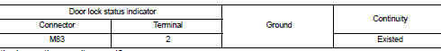
Is the inspection result normal? YES >> Replace door lock status indicator.
NO >> Repair or replace harness.
 Door lock and unlock switch
Driver side : Component Function Check
1.CHECK FUNCTION
1. Select “DOOR LOCK” of “BCM” using CONSULT-III.
2. Select “CDL LOCK SW”, “CDL UNLOCK SW” in “DATA MONITOR” mode.
3. Check that the functio ...
 Door request switch
Component Function Check
1.CHECK FUNCTION
1. Select “INTELLIGENT KEY” of “BCM” using CONSULT-III.
2. Select “REQ SW-DR”, “REQ SW-AS” in “DATA MONITOR” mode.
3. Check that the function operates nor ...
Other materials:
System
System Diagram
System Description
Supplemental Restraint System (SRS) activates air bag module and seat belt
pre-tensioner when it detects a
frontal collision or a side collision that is more than the specified limit.
Together with other safety devices, it reduces the impact that occupant ...
P181E steering angle sensor
DTC Logic
DTC DETECTION LOGIC
DTC CONFIRMATION PROCEDURE
1.PRECONDITIONING
If “DTC CONFIRMATION PROCEDURE” has been previously conducted, always turn
ignition switch OFF and
wait at least 10 seconds before conducting the next test.
>> GO TO 2.
2.DTC REPRODUCTION PROCEDURE
With ...
Combination switch output circuit
Diagnosis Procedure
1.CHECK OUTPUT 1 - 5 CIRCUIT FOR OPEN
1. Turn ignition switch OFF.
2. Disconnect BCM and combination switch connectors.
3. Check continuity between BCM harness connector and combination switch harness
connector.
Does continuity exist?
YES >> GO TO 2.
NO >> ...
