Nissan Juke Service and Repair Manual : Door lock actuator
Driver side
DRIVER SIDE : Component Function Check
1.CHECK FUNCTION
1. Select “DOOR LOCK” of “BCM” using CONSULT-III.
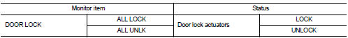
2. Select “DOOR LOCK” in “ACTIVE TEST” mode.
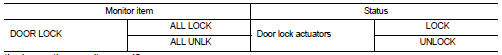
3. Check that the function operates normally according to the following conditions.
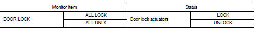
Is the inspection result normal? YES >> Door lock actuator is OK.
NO >> Refer to DLK-249, "DRIVER SIDE : Diagnosis Procedure".
DRIVER SIDE : Diagnosis Procedure
1.CHECK DOOR LOCK ACTUATOR INPUT SIGNAL
1. Turn ignition switch OFF.
2. Disconnect front door lock assembly (driver side) connector.
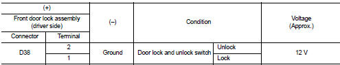
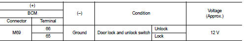
3. Check voltage between front door lock assembly (driver side) harness connector and ground.
Is the inspection result normal? YES >> Replace front door lock assembly (driver side).
NO >> GO TO 2.
2.CHECK DOOR LOCK ACTUATOR CIRCUIT
1. Disconnect BCM connector and all door lock assembly connector.
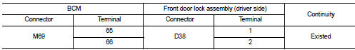
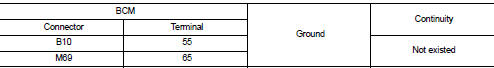
2. Check continuity between BCM harness connector and front door lock assembly (driver side) harness connector.
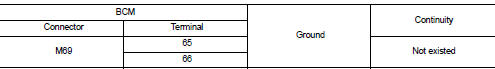
3. Check continuity between BCM harness connector and ground.
Is the inspection result normal? YES >> GO TO 3.
NO >> Repair or replace harness.
3.CHECK BCM OUTPUT SIGNAL
1. Connect BCM connector.
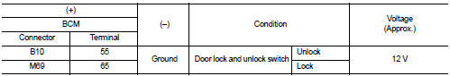
2. Check voltage between BCM harness connector and ground.
Is the inspection result normal? YES >> Check for internal short of each door lock actuator.
NO >> Replace BCM. Refer to BCS-93, "Removal and Installation".
Passenger side
PASSENGER SIDE : Component Function Check
1.CHECK FUNCTION
1. Select “DOOR LOCK” of “BCM” using CONSULT-III.
2. Select “DOOR LOCK” in “ACTIVE TEST” mode.
3. Check that the function operates normally according to the following conditions.
Is the inspection result normal? YES >> Door lock actuator is OK.
NO >> Refer to DLK-249, "DRIVER SIDE : Diagnosis Procedure".
PASSENGER SIDE : Diagnosis Procedure
1.CHECK DOOR LOCK ACTUATOR INPUT SIGNAL
1. Turn ignition switch OFF.
2. Disconnect front door lock assembly (passenger side) connector.
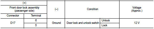
3. Check voltage between front door lock assembly (passenger side) harness connector and ground.
Is the inspection result normal? YES >> Replace front door lock assembly (passenger side).
NO >> GO TO 2.
2.CHECK DOOR LOCK ACTUATOR CIRCUIT
1. Disconnect BCM connector and all door lock assembly connector.
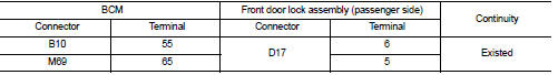
2. Check continuity between BCM harness connector and front door lock assembly (passenger side) harness connector.
3. Check continuity between BCM harness connector and ground.
Is the inspection result normal? YES >> GO TO 3.
NO >> Repair or replace harness.
3.CHECK BCM OUTPUT SIGNAL
1. Connect BCM connector.
2. Check voltage between BCM harness connector and ground.
Is the inspection result normal? YES >> Check for internal short of each door lock actuator.
NO >> Replace BCM. Refer to BCS-93, "Removal and Installation".
Rear LH
REAR LH : Component Function Check
1.CHECK FUNCTION
1. Select “DOOR LOCK” of “BCM” using CONSULT-III.
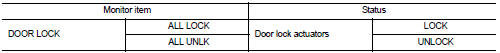
2. Select “DOOR LOCK” in “ACTIVE TEST” mode.
3. Check that the function operates normally according to the following conditions.
Is the inspection result normal? YES >> Door lock actuator is OK.
NO >> Refer to DLK-249, "DRIVER SIDE : Diagnosis Procedure".
REAR LH : Diagnosis Procedure
1.CHECK DOOR LOCK ACTUATOR INPUT SIGNAL
1. Turn ignition switch OFF.
2. Disconnect rear door lock assembly LH connector.
3. Check voltage between rear door lock assembly LH harness connector and ground.
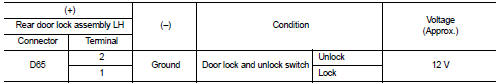
Is the inspection result normal? YES >> Replace rear door lock assembly LH.
NO >> GO TO 2.
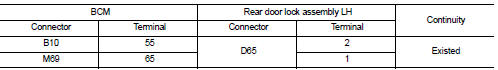
2.CHECK DOOR LOCK ACTUATOR CIRCUIT
1. Disconnect BCM connector and all door lock assembly connector.
2. Check continuity between BCM harness connector and rear door lock assembly LH harness connector.
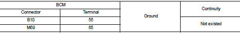
3. Check continuity between BCM harness connector and ground.
Is the inspection result normal? YES >> GO TO 3.
NO >> Repair or replace harness.
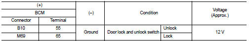
3.CHECK BCM OUTPUT SIGNAL
1. Connect BCM connector.
2. Check voltage between BCM harness connector and ground.
Is the inspection result normal? YES >> Check for internal short of each door lock actuator.
NO >> Replace BCM. Refer to BCS-93, "Removal and Installation".
Rear RH
REAR RH : Component Function Check
1.CHECK FUNCTION
1. Select “DOOR LOCK” of “BCM” using CONSULT-III.
2. Select “DOOR LOCK” in “ACTIVE TEST” mode.
3. Check that the function operates normally according to the following conditions.
Is the inspection result normal? YES >> Door lock actuator is OK.
NO >> Refer to DLK-249, "DRIVER SIDE : Diagnosis Procedure".
REAR RH : Diagnosis Procedure
1.CHECK DOOR LOCK ACTUATOR INPUT SIGNAL
1. Turn ignition switch OFF.
2. Disconnect rear door lock assembly RH connector.
3. Check voltage between rear door lock assembly RH harness connector and ground.
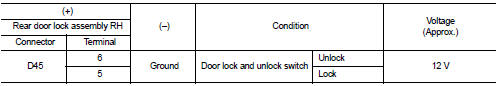
Is the inspection result normal? YES >> Replace rear door lock assembly RH.
NO >> GO TO 2.
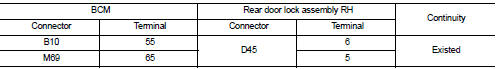
2.CHECK DOOR LOCK ACTUATOR CIRCUIT
1. Disconnect BCM connector and all door lock assembly connector.
2. Check continuity between BCM harness connector and rear door lock assembly RH harness connector.
3. Check continuity between BCM harness connector and ground.
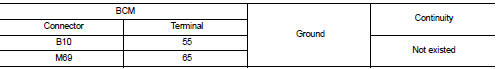
Is the inspection result normal? YES >> GO TO 3.
NO >> Repair or replace harness.
3.CHECK BCM OUTPUT SIGNAL
1. Connect BCM connector.
2. Check voltage between BCM harness connector and ground.
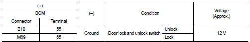
Is the inspection result normal? YES >> Check for internal short of each door lock actuator.
NO >> Replace BCM. Refer to BCS-93, "Removal and Installation".
 Buzzer (combination meter)
Component Function Check
1.CHECK FUNCTION
1. Select “INTELLIGENT KEY” of “BCM” using CONSULT-III.
2. Select “INSIDE BUZZER” in “ACTIVE TEST” mode.
3. Check that the function operates normally acco ...
 Door lock and unlock switch
Component Function Check
1.CHECK FUNCTION
1. Select “DOOR LOCK” of “BCM” using CONSULT-III.
2. Select “CDL LOCK SW”, “CDL UNLOCK SW” in “DATA MONITOR” mode.
3. Check that the function operates nor ...
Other materials:
Rear window defogger does not operate but both door
mirror defoggers operate
Diagnosis Procedure
1.CHECK REAR WINDOW DEFOGGER
Check rear window defogger.
Refer to DEF-31, "Component Function Check".
Is the inspection result normal?
YES >> GO TO 2.
NO >> Repair or replace the malfunctioning parts.
2.CONFIRM THE OPERATION
Confirm the opera ...
Cylinder block
Disassembly and Assembly
PREPARING USED ENGINE
The engine should be cleaned and drained (oil and water).
Leave on the used engine or include in the return box:
• Oil filter
• Oil pressure switch
• Water pump
• Fuel injection pump
• Rail
• Injectors
• Glow plugs
• Oil level gauge
• Vacu ...
Headlamp washer relay
Component Inspection
1.CHECK HEADLAMP WASHER RELAY
1. Turn the ignition switch OFF.
2. Remove headlamp washer relay.
3. Apply battery voltage to headlamp washer relay between terminals 1 and 2.
4. Check continuity of headlamp washer relay.
Is the inspection result normal?
YES >> Headl ...
